Capsule Tool
- Summary
- Abstract
- Description
- Claims
- Application Information
AI Technical Summary
Benefits of technology
Problems solved by technology
Method used
Image
Examples
embodiment 1
Preferred Embodiment 1
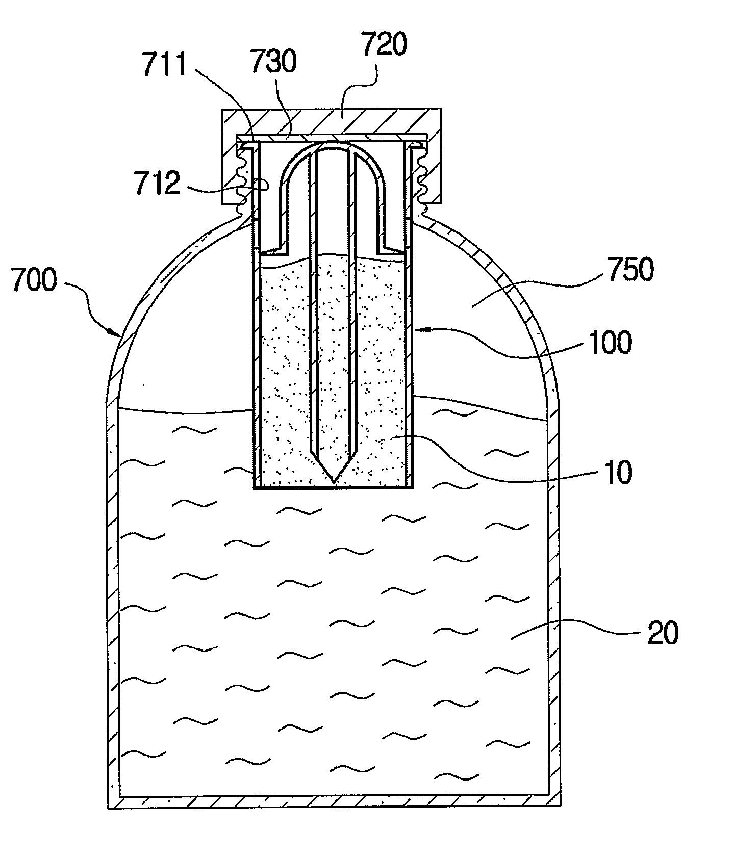
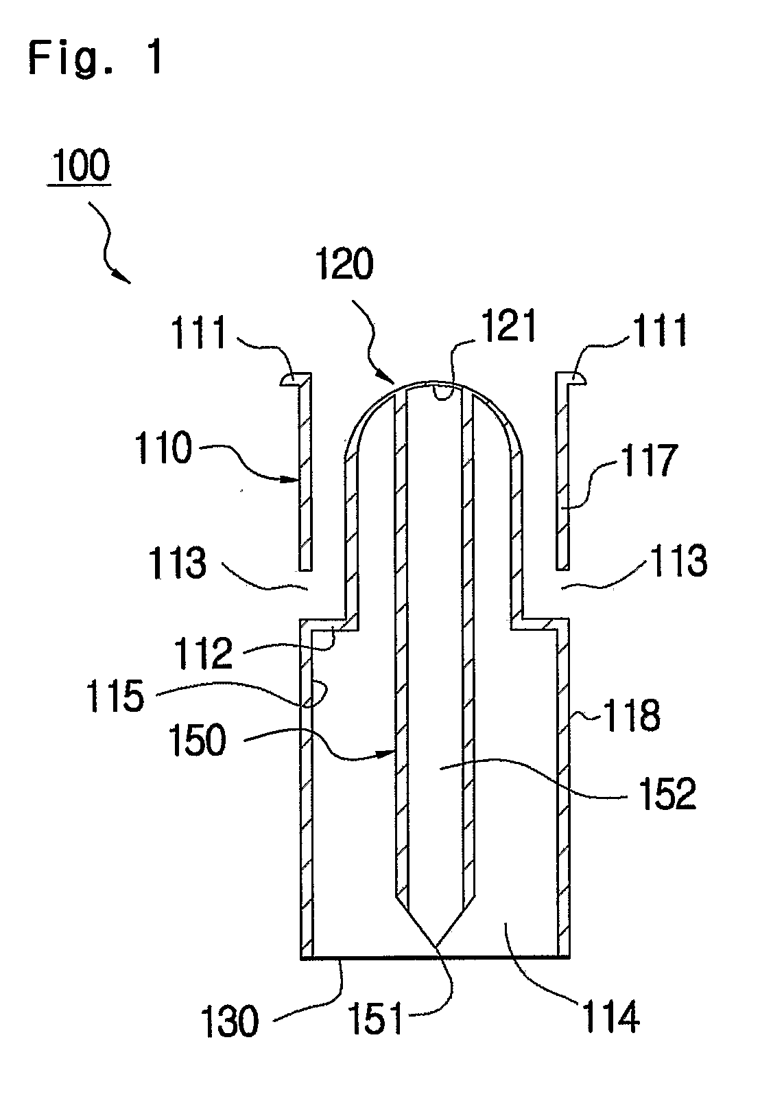
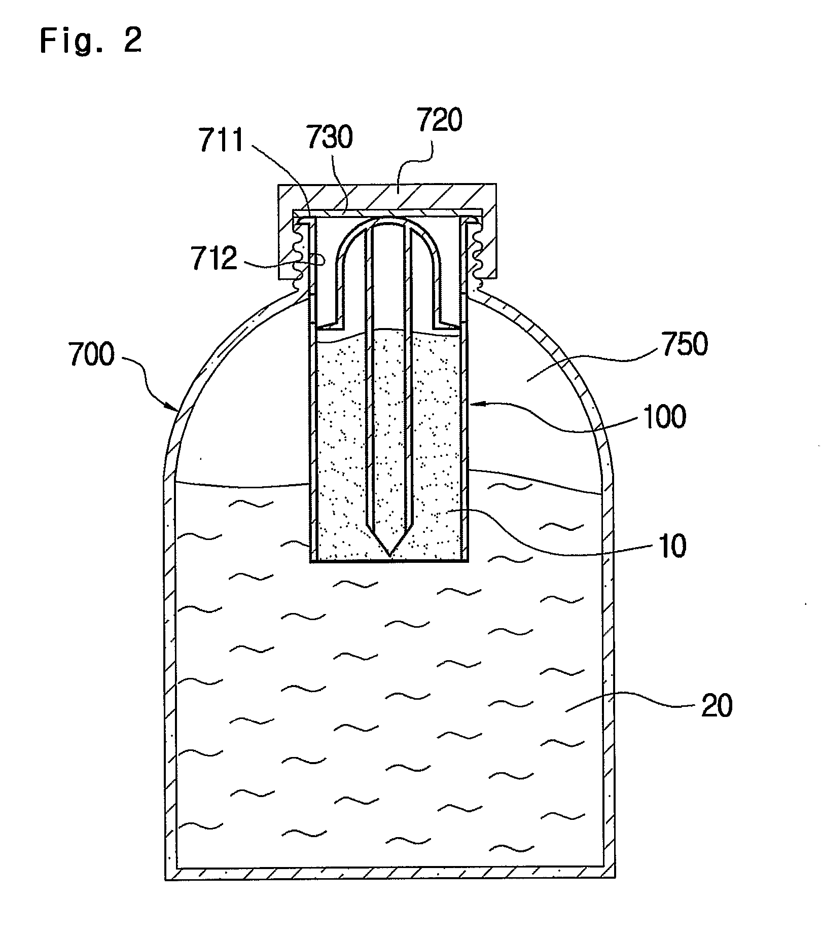
[0033]FIG. 1 is a cross-sectional view of a capsule container 100 according to the present invention. FIG. 2 is a cross-sectional view of the capsule container 100 shown in FIG. 1 assembled to a beverage bottle 700. FIG. 3 is a cross-sectional view of the capsule container shown in FIG. 2 when it is used.
[0034] Referring now to FIGS. 1 to 3, the capsule container 100 according to the present invention includes a receiving member 110, a pressing member 120 integrally formed on the inner periphery of the receiving member 110, a vertically movable member 150 installed inside of the pressing member 120, and a shielding membrane 130 finishing the lower side of the receiving member 110.
[0035] More concretely, the receiving member 110 has a cylindrical shape having both ends open, and the outer periphery 118 of the receiving member 110 has the same diameter and shape as those of the inner periphery 712 of the opening formed on a bottle 700. The upper side of the rec...
embodiment 2
Preferred Embodiment 2
[0050]FIG. 4 is a partially cross-sectional view of a capsule container 200 according to another preferred embodiment of the present invention. FIG. 5 is a cross-sectional view of the capsule container 200 shown in FIG. 4 when it is used.
[0051] Referring now to FIGS. 4 and 5, the capsule container 200 is briefly constructed to have a receiving member 110, a pressing member 120 formed on the upper side which is slided and inserted in the receiving member 110, a vertically movable member 150 installed under the pressing member 120, and a shielding membrane 130 finishing the lower end of the receiving member 110.
[0052] More concretely, the receiving member 110 has a similar structure to that of Preferred Embodiment 1, and is characterized by being equipped with a partition 112 dividing the receiving member 110 into upper and lower portions, a hollow portion vertically penetrating through the central part of the partition 112, a cylindrical guide member 220 exten...
embodiment 3
Preferred Embodiment 3
[0059]FIG. 6 is a cross-sectional view of a capsule container 300 according to still another preferred embodiment of the present invention, which shows modified designing and construction of a capsule container in the above Preferred Embodiment 2.
[0060] The capsule container shown in FIG. 6 has a similar construction to that of Preferred Embodiment 2, provided that the upper side of the guide member 220 is cut to have fixed thickness and depth, and therefore, an enlarged end 324 having an extended inner diameter as well as a stepped portion 325 having the shape of a locking portion are formed on the enlarged end 324 and the lower part of the enlarged end 324.
[0061] The pressing member 120 further includes a locking portion 326 which is horizontally extended from the upper side of the pressing member, where the locking portion 326 has the same size as that of the enlarged end 324. When the pressing member 120 and vertically movable member 150 break the sheldin...
PUM
 Abstract
Description
Claims
Application Information
 - R&D
- Intellectual Property
- Life Sciences
- Materials
- Tech Scout
- Unparalleled Data Quality
- Higher Quality Content
- 60% Fewer Hallucinations
Browse by: Latest US Patents, China's latest patents, Technical Efficacy Thesaurus, Application Domain, Technology Topic, Popular Technical Reports.
© 2025 PatSnap. All rights reserved.Legal|Privacy policy|Modern Slavery Act Transparency Statement|Sitemap|About US| Contact US: help@patsnap.com


