

Ball screw
a ball screw and screw body technology, applied in the field of ball screws, can solve problems such as the problem of circling oil, and achieve the effects of easy and precise formation of the bridge member, high work difficulty, and complicated configuration
- Summary
- Abstract
- Description
- Claims
- Application Information
AI Technical Summary
Benefits of technology
Problems solved by technology
Method used
Image

Examples
Embodiment Construction
[0024] Embodiments of the present disclosure will be described with reference to accompanying drawings.
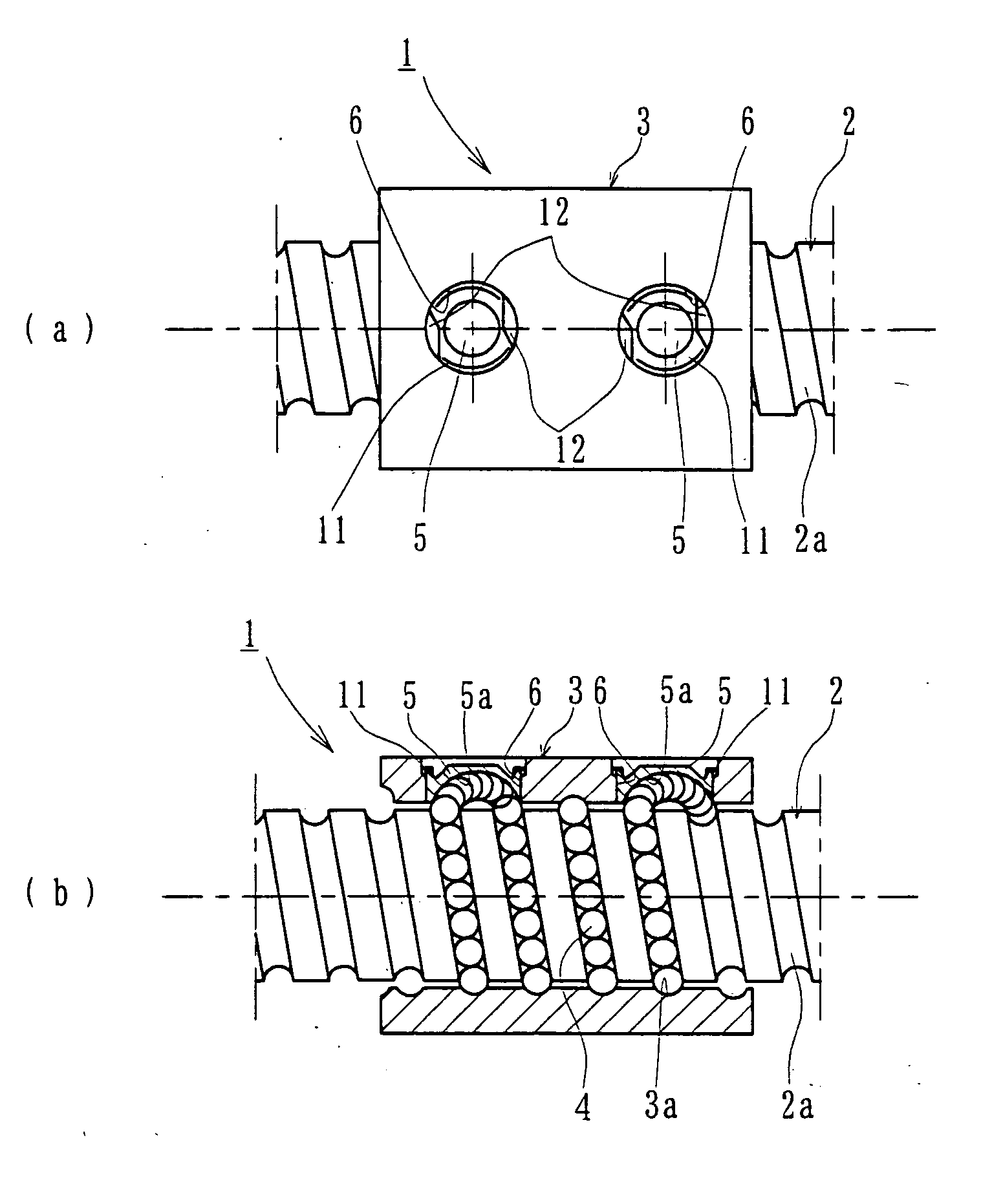
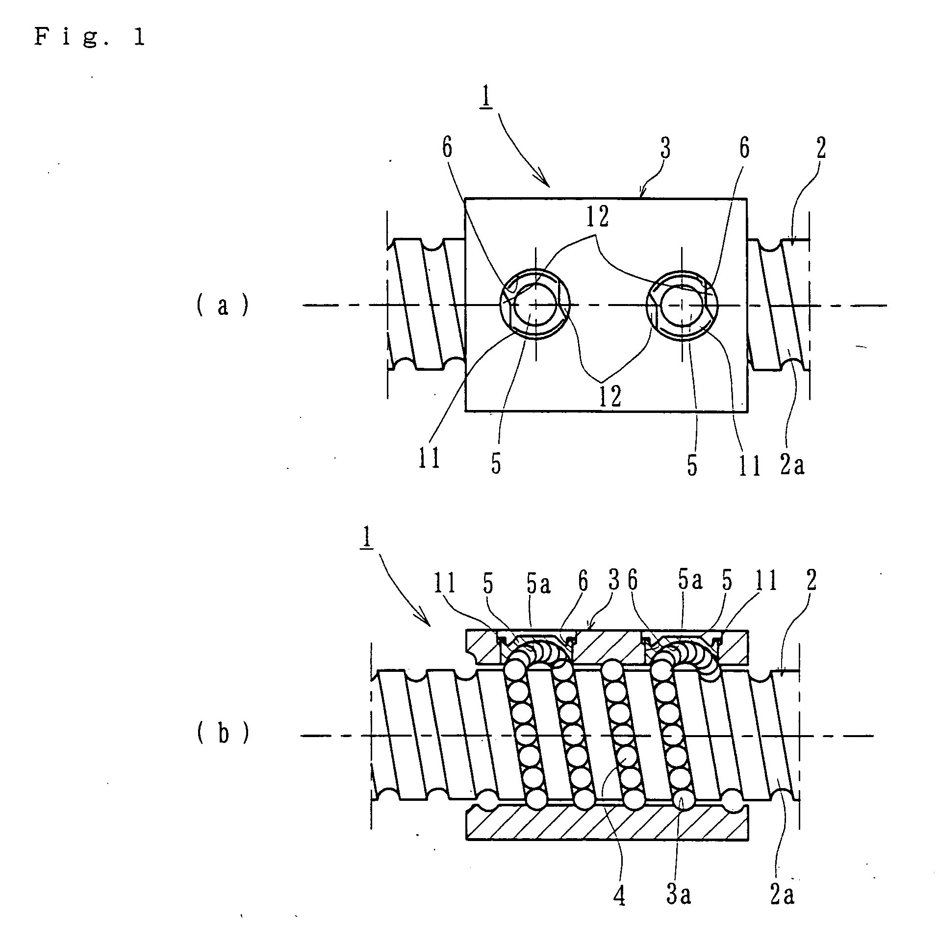
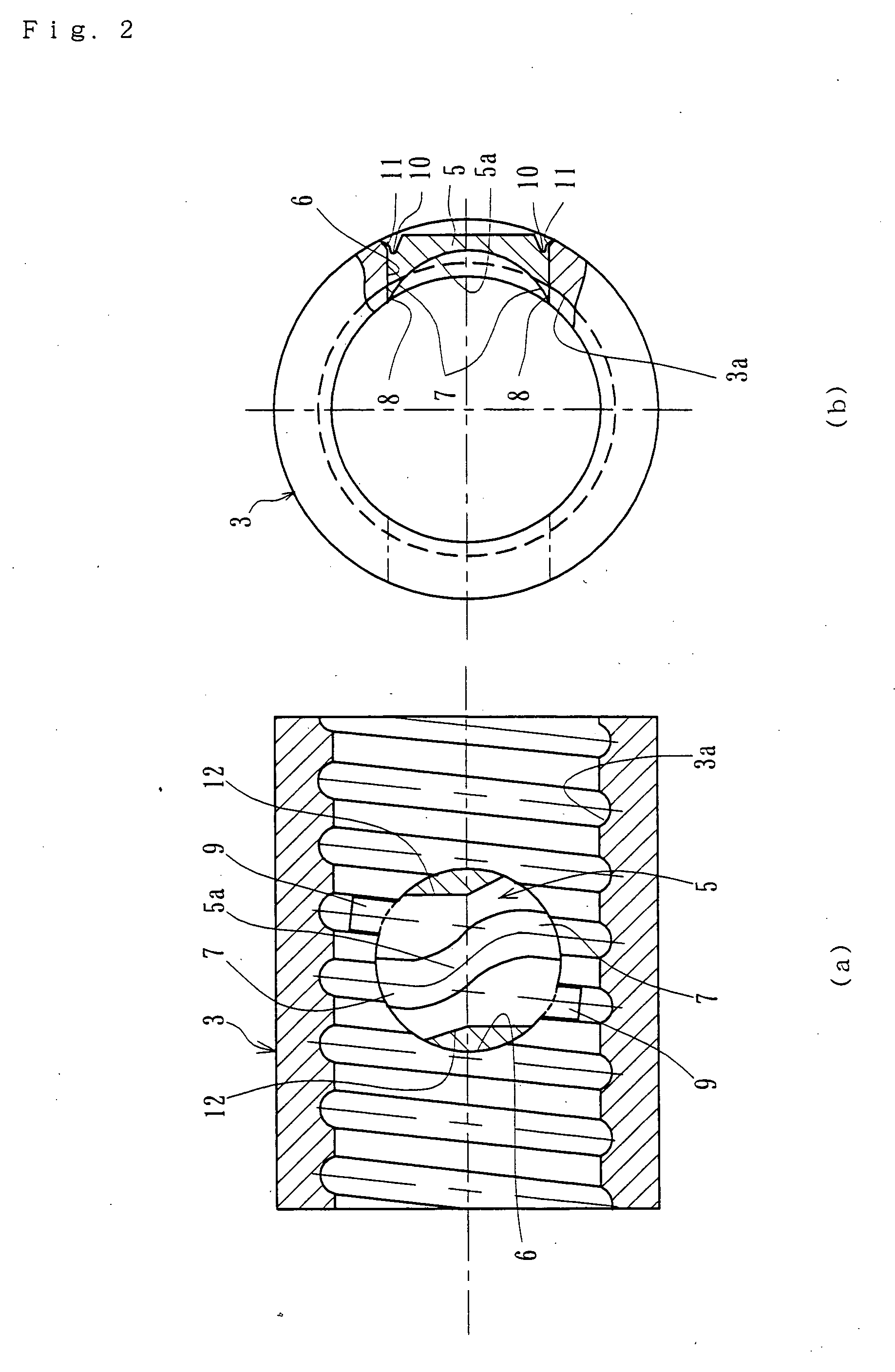
[0025]FIG. 1(a) is a plan view of one embodiment of the ball screw of the present disclosure. FIG. 1(b) is a longitudinal section view of the ball screw of FIG. 1(a). FIG. 2(a) is a longitudinal section view of a nut of the present disclosure. FIG. 2(b) is a partial broken end view of FIG. 2(a).
[0026] The ball screw 1 includes a screw shaft 2 formed with a helical screw groove 2a on its outer circumferential surface. A nut 3 is adapted to fit onto the screw shaft 2. The nut 3 has a helical screw groove 3a on its inner circumferential surface. A large number of balls 4 are contained in a rolling passage formed between oppositely arranged screw grooves 2a and 3a. A bridge member 5 has a connecting groove 5a to connect mutually adjacent rolling grooves 3a of the nut 3 by one round.
[0027] The longitudinal section configuration of each of the screw grooves 2a and 3a may be of a circu...
PUM
 Abstract
Description
Claims
Application Information