Electro-mechanical coaxial valve

a coaxial valve and electric motor technology, applied in the direction of multiple way valves, valve details, valve arrangements, etc., can solve the problems of considerable pressure loss, not easy to provide for electric motor actuation,

Inactive Publication Date: 2004-10-12
NASA
View PDF12 Cites 48 Cited by
  • Summary
  • Abstract
  • Description
  • Claims
  • Application Information

AI Technical Summary

Problems solved by technology

Since coaxial valves usually contain only one moving part it has not been easy to provide for electric motor actuation.
The units (bearing, rotor, gearing) which are incorporated directly in the flow channel, impair the

Method used


Image

  • Electro-mechanical coaxial valve
  • Electro-mechanical coaxial valve
  • Electro-mechanical coaxial valve

Examples


Embodiment Construction

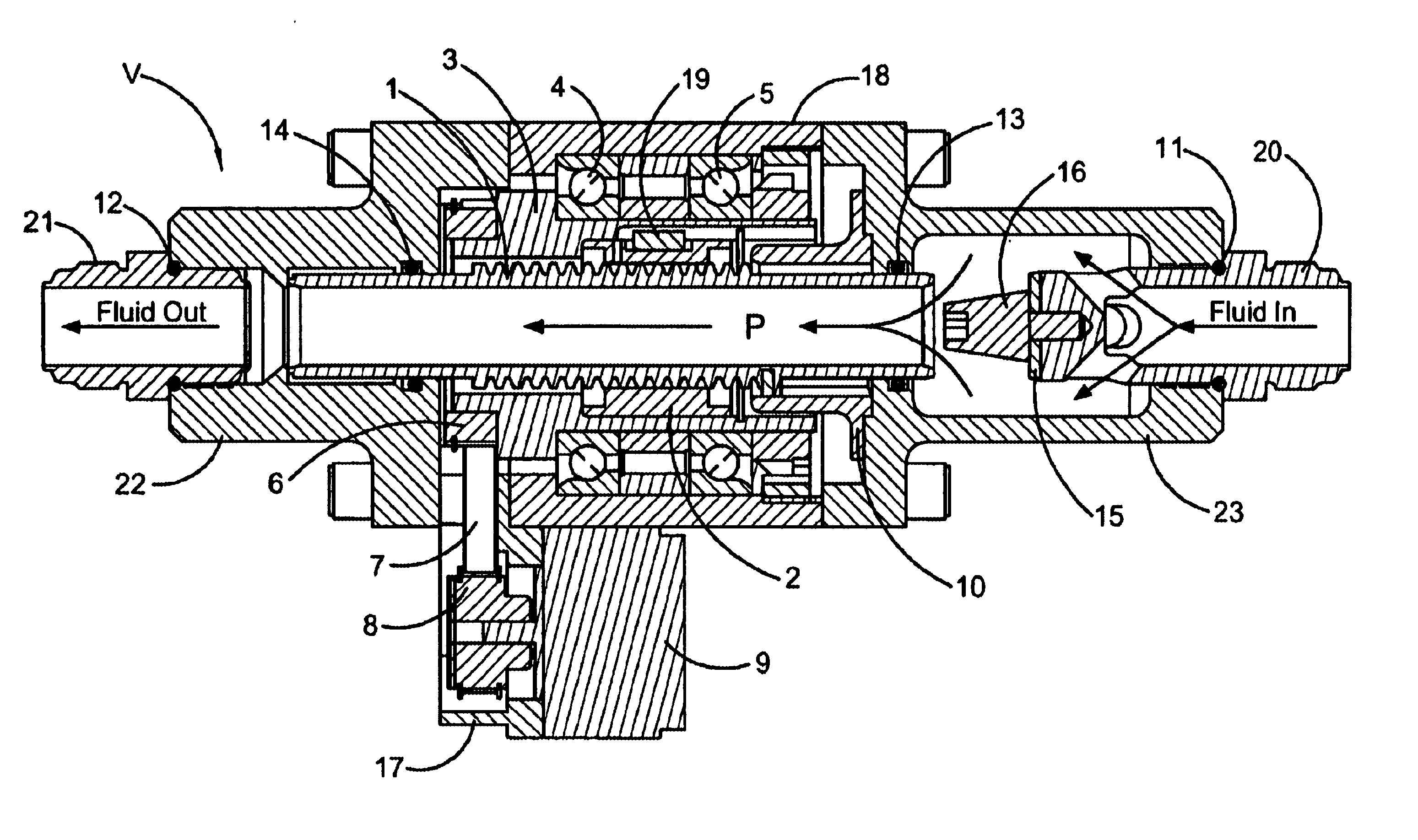
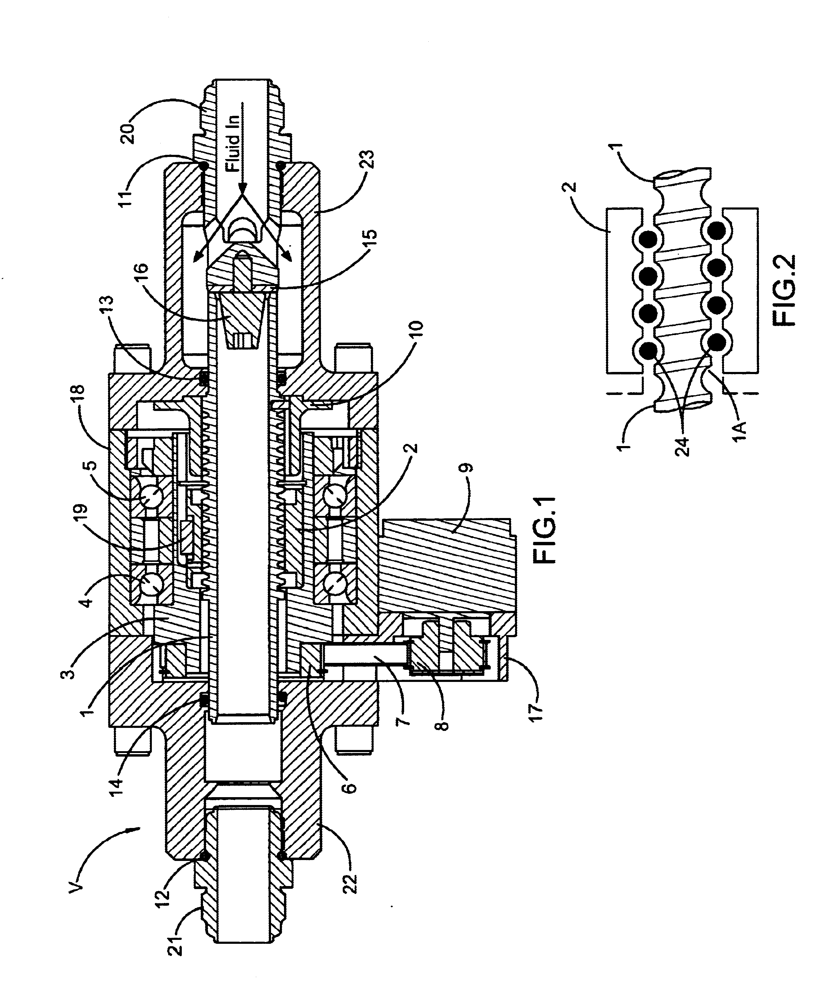
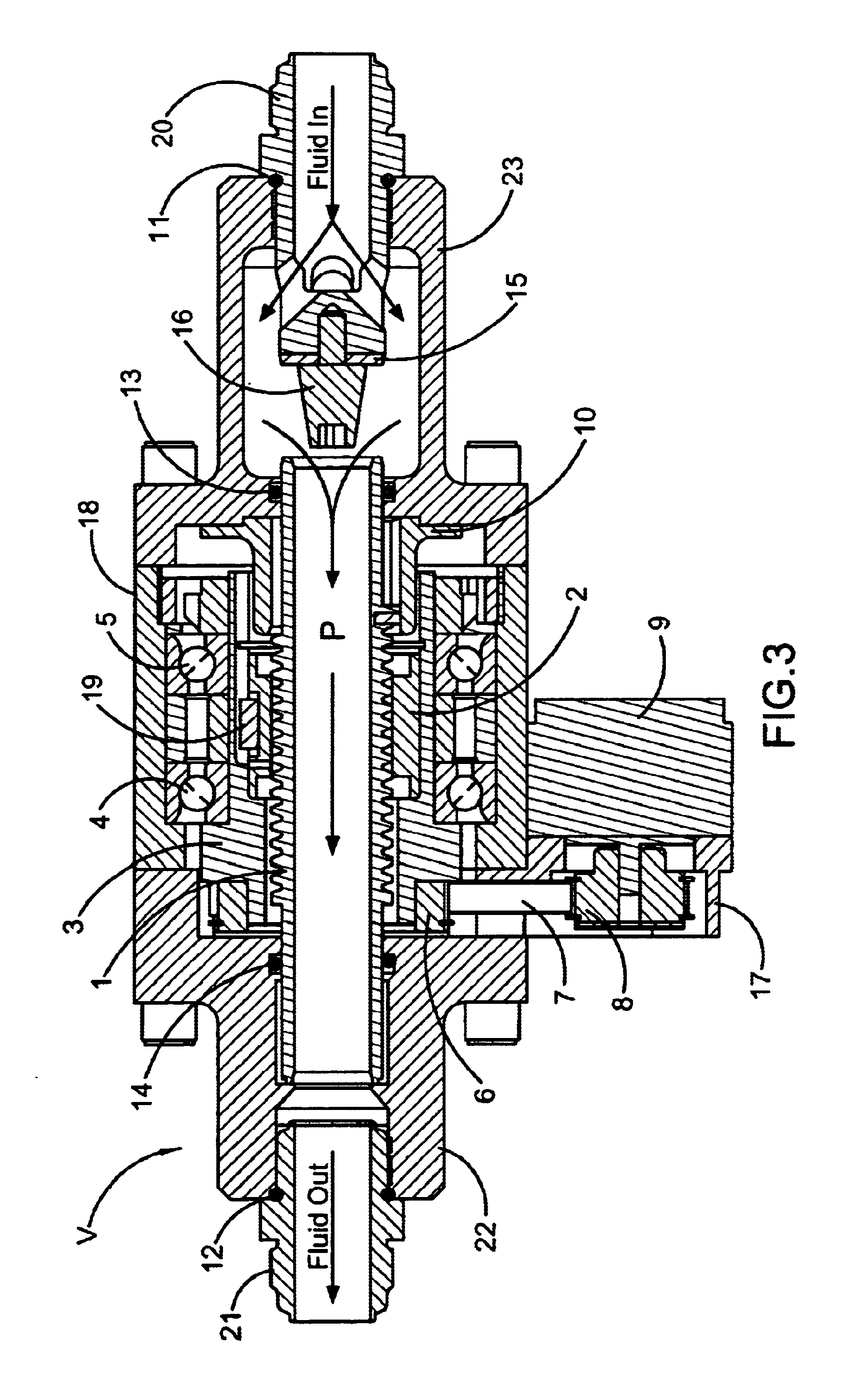
As illustrated in FIG. 1 a motor 9 is connected to the valve, V, through a drive pulley 8, timing belt 7, and driven pulley 6. Motor 9 is supported by a bracket 17 bolted to the valve body 18. A driven pulley 6 is bolted to a sleeve 3 that also houses a ball nut 2. Sleeve 3 is mounted in bearings 4 and 5 fixed in valve body 18. Ball nut 2 is retained and made to rotate with the sleeve 3 by use of a key 19. Passing through ball nut 2 is a hollow cylindrical ball screw 1 that functions as both a valve actuator and a flow passage for be valve. Ball screw [or control tube] 1 is keyed to the valve body through an anti-rotation device 10 that prevents rotation of the ball screw, but allows the ball screw to translate axially in the valve when the ball nut 2 is rotated Ball screw [i.e., control tube] 1 has a precision ground or rolled external helical groove or threads 1A acting as an inner race. Ball nut 2 has internal grooves or threads that act as an outer race. Precision steel balls 24...


PUM


Abstract

Coaxial valves usually contain only one moving part. It has not been easy, then, to provide for electric motor actuation. Many actuators being proposed involve designs which lead to bulky packages. The key facing those improving coaxial valves is the provision of suitable linear actuation. The valve herein includes a valve housing with a flow channel therethrough. Arranged in the flow channel is a closing body. In alignment with the closing body is a ball screw actuator which includes a ball nut and a cylindrical screw. The ball nut surrounds a threaded portion of the cylindrical screw. The cylindrical screw is provided with a passageway therethrough through which fluid flows. The cylindrical screw is disposed in the flow channel to become a control tube adapted to move toward and away from the valve seat. To rotate the ball nut an actuating drive is employed driven by a stepper motor.

Description

CROSS-REFERENCE TO A RELATED APPLICATIONSThere are no applications related to this applicationSTATEMENT REGARDING FEDERALLY-SPONSORED RESEARCH OR DEVELOPMENTThe invention described in this patent was made by an employee of the United States Government and may be manufactured and used by or for the Government for governmental purposes without the payment of any royalties.1. Field of the InventionThis invention relates to a coaxial valve which is especially suited for use in propulsion in aircraft and spacecraft for the control of flow of liquids and gases under conditions wherein solenoids are not as effective.2. Background of the InventionThe most significant use for coaxial valves is in their high flow capability and pressure balanced control element. This means that hydraulic forces against the control element remain balanced in both open and closed positions and the transition between, allowing smooth, controlled, predictable and fast actuation speeds. The valves operate by urgin...

Claims


Application Information

Patent Timeline
IPC IPC(8): F16K1/00F16K1/12
CPCF16K1/123
Inventor PATTERSON, PAUL R.
Owner NASA
Why Eureka
Try Eureka