Dual-injector fuel injection engine

a fuel injection engine and injector technology, applied in the direction of machines/engines, electric control, combustion air/fuel air treatment, etc., can solve the problems of fuel leakage from the sealed portion, cumbersome assembly, etc., and achieve the effect of high mounting accuracy and easy maintenan

Active Publication Date: 2006-09-21
YAMAHA MOTOR CO LTD +1
View PDF41 Cites 25 Cited by
  • Summary
  • Abstract
  • Description
  • Claims
  • Application Information

AI Technical Summary

Benefits of technology

[0011] The present invention has been made to solve the above problems, and has as its object to provide a dual-injector fuel injection engine in which, while two types of injectors can be mounted in the engine in a compact manner, the intake pipe injector and a delivery pipe can be mounted and maintained easily with high mounting accuracy.

Problems solved by technology

Accordingly, the number of assembling steps increases to make the assembly cumbersome.
The problem of overlapping operations thus occurs not only in the manufacture of the engine but also in the maintenance as well.
If the intake pipe injector and its delivery pipe are aligned incompletely, fuel may leak from the sealed portion partly because the fuel is pressurized excessively.

Method used


Image

  • Dual-injector fuel injection engine
  • Dual-injector fuel injection engine
  • Dual-injector fuel injection engine

Examples


first embodiment

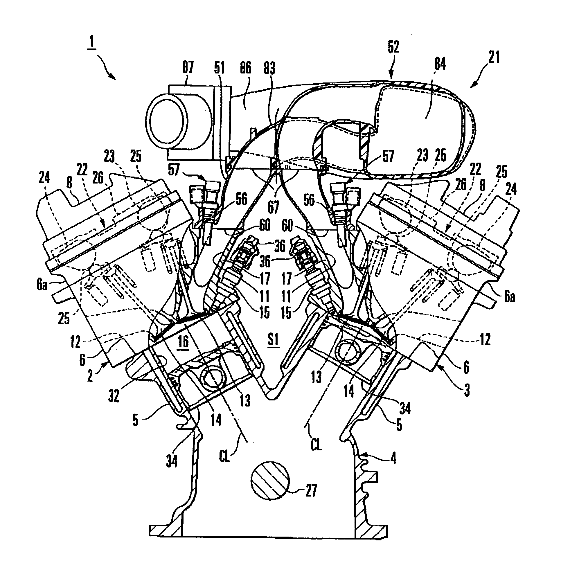
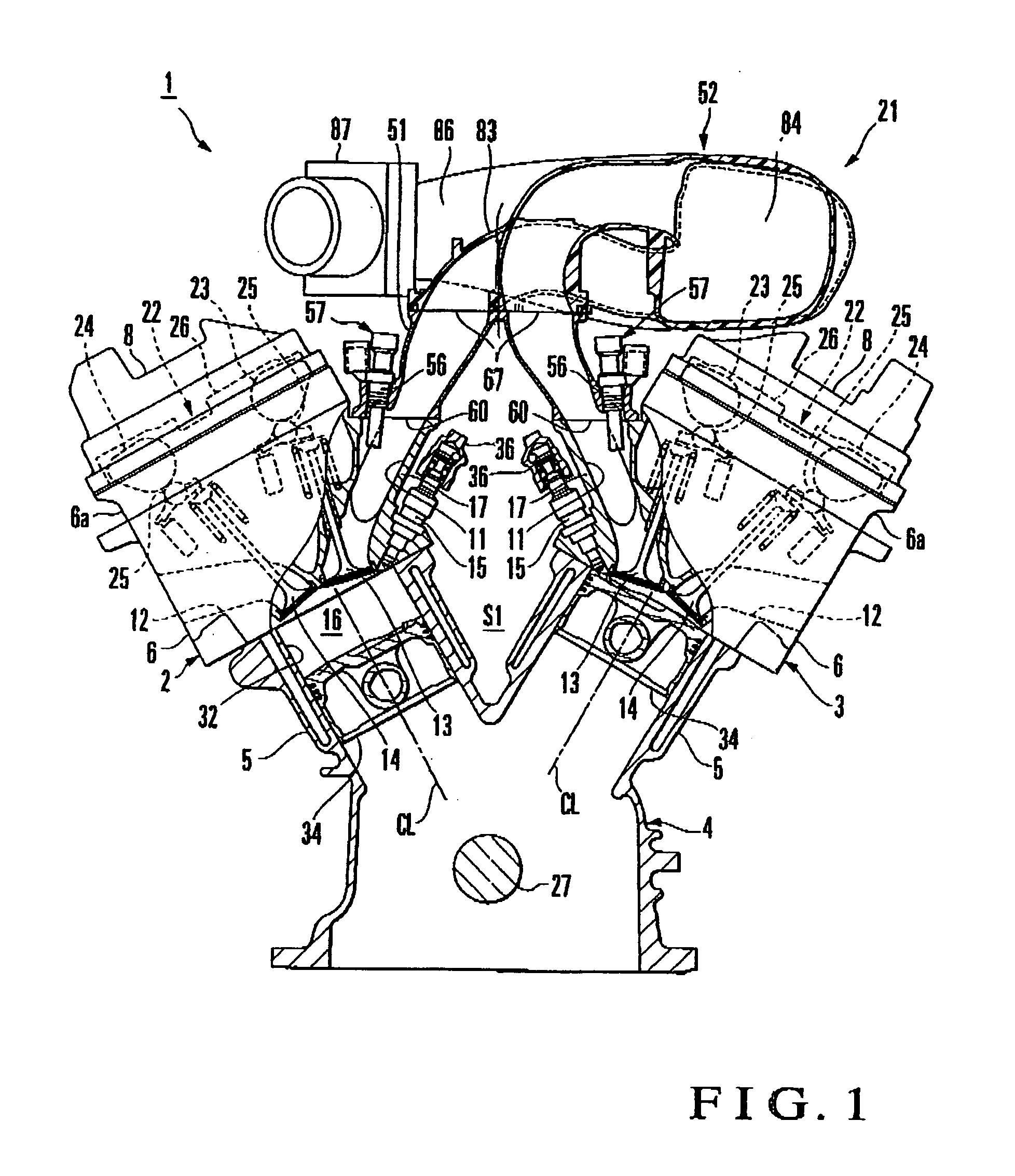
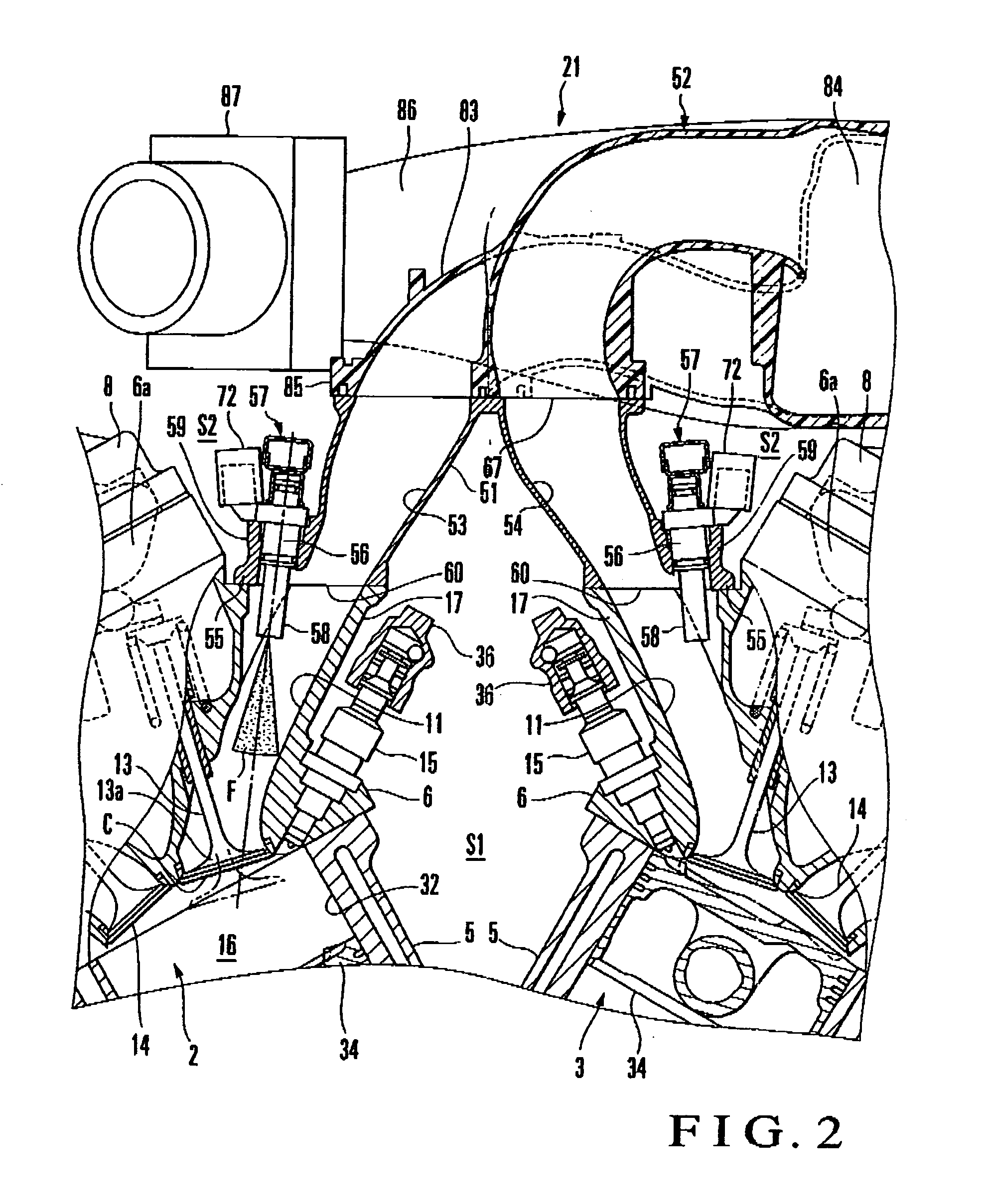
[0024] A dual-injector fuel injection engine according to one embodiment of the present invention will be described with reference to FIGS. 1 to 8.

[0025]FIGS. 1 and 2 show the main part of a dual-injector fuel injection engine according to the present invention. FIG. 3 shows a state wherein an intake manifold is mounted, and FIG. 4 shows a state wherein the intake manifold is removed. FIGS. 5 to 8 show a sub-Intake manifold.

[0026] A dual-injector fuel injection engine 1 according to this embodiment is a V-type 6-cylinder engine to be mounted in an automobile, and comprises a first cylinder row 2 located on the left side in FIG. 1 and a second cylinder row 3 located on the right side in FIG. 1. The cylinder rows 2 and 3 have the same arrangement, and accordingly the first cylinder row 2 will be described in detail. The respective members of the second cylinder row 3 are denoted by the same reference numerals as in the first cylinder row 2, and a description thereof will be omitted....

second embodiment

[0081] An intake manifold can be formed as shown in FIG. 9 or 10.

[0082]FIGS. 9 and 10 show other embodiments. In FIGS. 9 and 10, the same or equivalent members as those described with reference to FIGS. 1 to 8 are denoted by the same reference numerals, and a detailed description thereof will be omitted as needed.

[0083] An intake manifold 21 shown in each of FIGS. 9 and 10 comprises a main intake manifold 91 having a structure different from that of the first embodiment, and is provided with surge tanks 92 and 93 for the respective cylinder rows. This will be described in detail. Of the main intake manifold 91 shown in FIG. 9, the surge tank 92 communicating with the intake passage of a first cylinder row 2 is located above a second cylinder row 3, and the surge tank 93 communicating with the intake passage of the second cylinder row 3 is located above the first cylinder row 2.

[0084] In the main intake manifold 91 shown in FIG. 10, the surge tank 92 communicating with the intake ...

third embodiment

[0087] The present invention can also be applied to a multi-cylinder engine having only one cylinder row, as shown in FIG. 11.

[0088]FIG. 11 shows still another embodiment. In FIG. 11, the same or equivalent members as those described with reference to FIGS. 1 to 10 are denoted by the same reference numerals, and a detailed description thereof will be omitted as needed.

[0089] A dual-injector fuel injection engine 95 shown in FIG. 11 is an in-line multi-cylinder engine having only one cylinder row. This engine 95 has almost the same structure as that of the V-type multi-cylinder engine 1 shown in FIGS. 1 to 8 except that the number of cylinder rows is different. Thus, a sub-intake manifold 51 of an intake manifold 21 employed in the dual-injector fuel injection engine 95 of this embodiment is formed of only one side of the sub-intake manifold 51 shown in the first embodiment so as to be connected to intake ports 11 of one cylinder row. A main intake manifold 52 has a pipe-shaped por...


PUM


Abstract

A dual-injector fuel injection engine includes a cylinder block, a cylinder head, an intake port, an intake manifold, a surge tank, an in-cylinder injector, an intake pipe injector, and first and second delivery pipes. The in-cylinder injector is positioned below the intake port, when seen from an axial direction of a crank shaft, and attached to the cylinder head. The intake pipe injector and the second delivery pipe are supported above the intake port, when seen from the axial direction of the crank shaft, by the intake manifold to be close to the intake port.

Description

BACKGROUND OF THE INVENTION [0001] The present invention relates to a dual-injector fuel injection engine in which fuel is injected into a combustion chamber and intake passage from respective injectors. [0002] Generally, in a conventional automobile engine, one fuel injector is provided to each cylinder. In an engine of this type, an injector which injects fuel directly into a combustion chamber and an injector which injects fuel into an intake passage may be provided in order to improve the output and fuel cost, as disclosed in, e.g., Japanese Patent Laid-open No. 11-315733 (to be merely referred to as reference 1 hereinafter) or 2002-48035 (to be merely referred to as reference 2 hereinafter). [0003] In the engine described in reference 1, an in-cylinder injector which injects fuel into the combustion chamber is attached to that lower end of a cylinder head which is close to a cylinder block. An injector which injects fuel (light oil) into an intake passage is attached to that si...

Claims


Application Information

Patent Timeline
Patent Type & Authority Applications(United States)
IPC IPC(8): F02B75/22F02M61/14
CPCF02B23/104F02B2275/16F02D41/3094F02M35/10045F02M35/10072F02M35/10085F02M35/10131F02M35/10177F02M35/10216F02M35/10268F02M35/10295F02M35/116F02M61/145F02M63/0225F02M69/044F02M69/046F02M69/465Y02T10/123F02B2075/125Y02T10/125Y02T10/12F02M69/00F02M61/14F02M55/00F02M63/00
Inventor SAEKI, TETSUYAABE, SHIZUOTSUCHIYA, TOMIHISATOMODA, TERUTOSHIKUROSAWA, SHINICHIKATOU, MASAKIYAMAGUCHI, AKIRASUZUKI, YUICHI
Owner YAMAHA MOTOR CO LTD
Why Eureka
Try Eureka