Synchronous toothed belt conveying mechanism

A technology of synchronous toothed belt and conveying mechanism, which is applied in the direction of conveyor, transportation and packaging, etc. It can solve the problems of complicated process, heavy disassembly and installation workload, and inability to apply synchronous toothed belt conveying mechanism, so as to improve the installation accuracy, The effect of simple operation and simple structure

Active Publication Date: 2021-04-02
SUZHOU DINNAR TECH FOR AUTOMATION CO LTD
View PDF13 Cites 0 Cited by
  • Summary
  • Abstract
  • Description
  • Claims
  • Application Information

AI Technical Summary

Problems solved by technology

[0005] However, although the above-mentioned structure is very convenient for loading and unloading flat belts, it cannot be applied to the synchronous toothed belt conveying mechanism. , when it is installed on the conveying mechanism again, it is difficult to realize the axis coincidence between the driving wheel and the transmission bearing, which is feasible for flat belts, because the installation accuracy requirements are not high, but for installation accuracy The synchronous toothed belt with high requirements will not work
In addition, no matter when removing or replacing the flat belt, it is necessary to pass the flat belt through the entire transmission mechanism (including driving wheels and driving wheels), and these driving wheels and driving wheels are installed on the frame. It is very large, so it is impossible for the flat belt to be inserted from the outside of the frame, so the driving wheel and / or drive wheel can only be removed from the frame, and then put on a new flat belt, and then installed on the frame; Caused the problem of large disassembly and installation workload and complicated process

Method used


Image

  • Synchronous toothed belt conveying mechanism
  • Synchronous toothed belt conveying mechanism
  • Synchronous toothed belt conveying mechanism

Examples


Embodiment 1

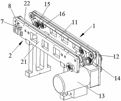
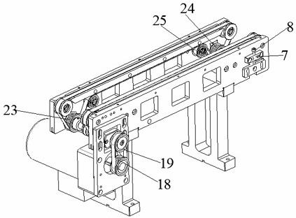
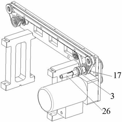
[0037] see Figure 1 to Figure 5 , a synchronous toothed belt conveying mechanism, comprising a first conveying mechanism 1 and a second conveying mechanism 2 arranged in parallel and symmetrically;

[0038] The first conveying mechanism includes a first conveying profile 11, a first synchronous toothed belt 12, a first driving mechanism and a first driven mechanism; the upper part of the first conveying profile has a first conveying channel, and the first The synchronous toothed belt penetrates the first conveying channel and forms a first conveying surface above the first conveying profile; the first driving mechanism includes a motor 13 and a first driving wheel 14, and the first driven mechanism includes At least one first driven wheel 15; one end of the first synchronous toothed belt is sleeved on the first driving wheel, the other end is sleeved on the first driven wheel, and at least one first The tensioning wheel 16 forms a belt transmission structure; the first tensi...


PUM


Abstract

The invention discloses a synchronous toothed belt conveying mechanism. The synchronous toothed belt conveying mechanism comprises a first conveying mechanism and a second conveying mechanism which are symmetrically arranged in parallel. Between the first conveying mechanism and the second conveying mechanism, a first transmission shaft is sleeved with a first driving wheel, and a second transmission shaft is sleeved with a second driving wheel. The first transmission shaft and the second transmission shaft are coaxially arranged and form a detachable fixed connection structure. By means of the first transmission shaft and the second transmission shaft which are coaxially arranged and form a detachable fixed connection structure, a channel is formed between the first driving wheel and thesecond driving wheel, and when a synchronous toothed belt needs to be disassembled and assembled, the belt can be loosened only by loosening a first tensioning wheel; and then the belt is taken out orsleeved from the channel between the first driving wheel and the second driving wheel, so that the operation is very simple and convenient.

Description

technical field [0001] The invention relates to the technical field of belt conveying, in particular to a synchronous toothed belt conveying mechanism. Background technique [0002] The synchronous toothed belt is referred to as the synchronous belt, also known as the timing belt, which is similar to the common V-belt, flat belt and other belt transmission methods, and is a flexible transmission form. In the prior art, the synchronous toothed belt is generally made of steel wire rope or glass fiber rope as the strength layer, covered with polyurethane or neoprene on the outside, and the inner circumference of the belt is toothed to mesh with the toothed pulley. Since the deformation of the strong layer is small after loading, the circumferential pitch of the toothed belt can be kept unchanged, so there is no relative sliding between the belt and the pulley, thus ensuring synchronous transmission and a stable transmission ratio. Compared with ordinary belt transmission, the ...

Claims


Application Information

Patent Timeline
Patent Type & Authority Applications(China)
IPC IPC(8): B65G23/44B65G23/04
CPCB65G23/04B65G23/44
Inventor 秦应化吴旭东刘奇
Owner SUZHOU DINNAR TECH FOR AUTOMATION CO LTD
Why Eureka
Try Eureka