Fluid flow control device having a throttling element seal
a technology of throttling element and flow control device, which is applied in the direction of valve member-seat contact, mechanical equipment, transportation and packaging, etc., can solve the problems of fluid leakage, prone to leakage of fluid, and the formation of conventional primary seals formed by throttling elements pressed against valve seat rings
- Summary
- Abstract
- Description
- Claims
- Application Information
AI Technical Summary
Benefits of technology
Problems solved by technology
Method used
Image

Examples
Embodiment Construction
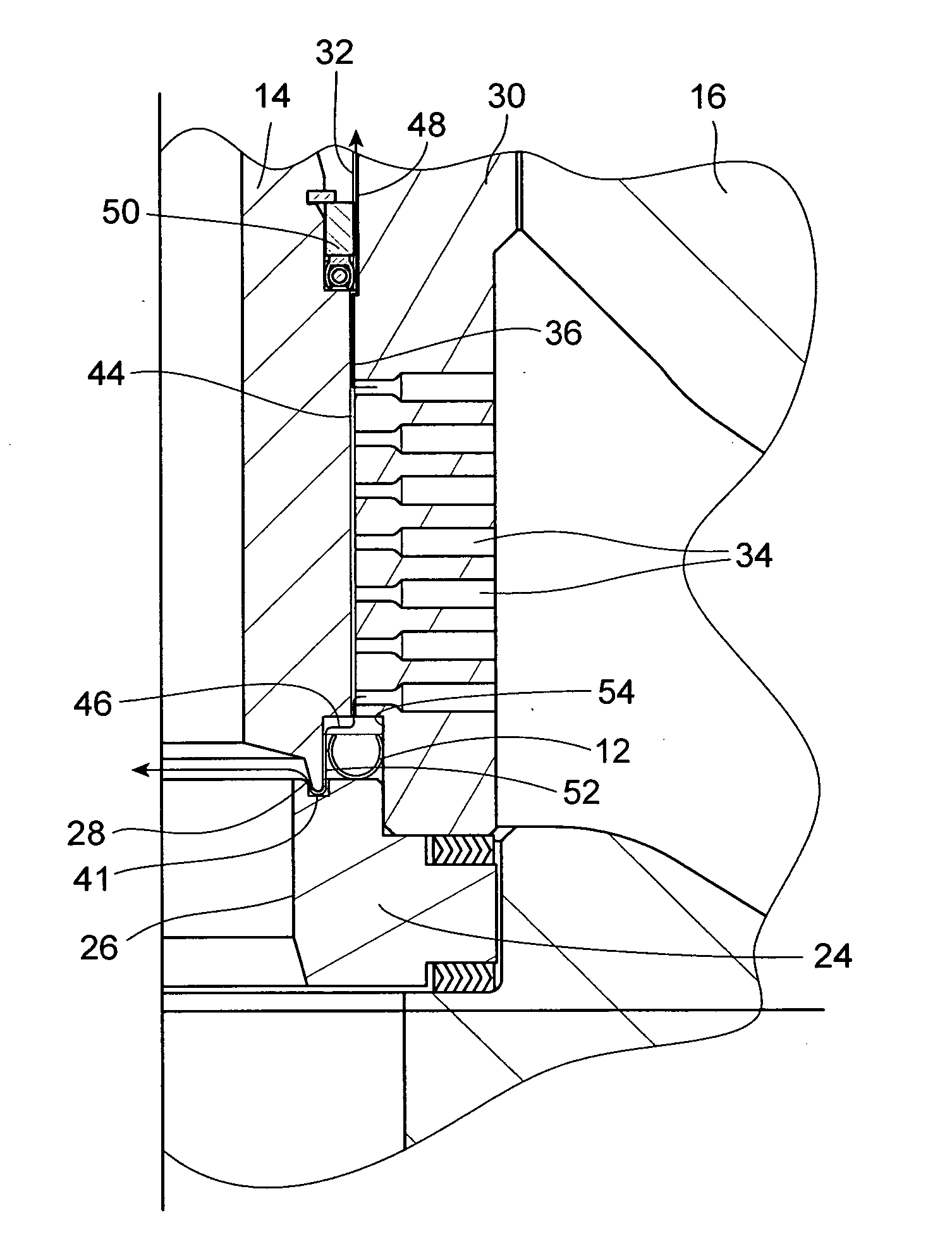
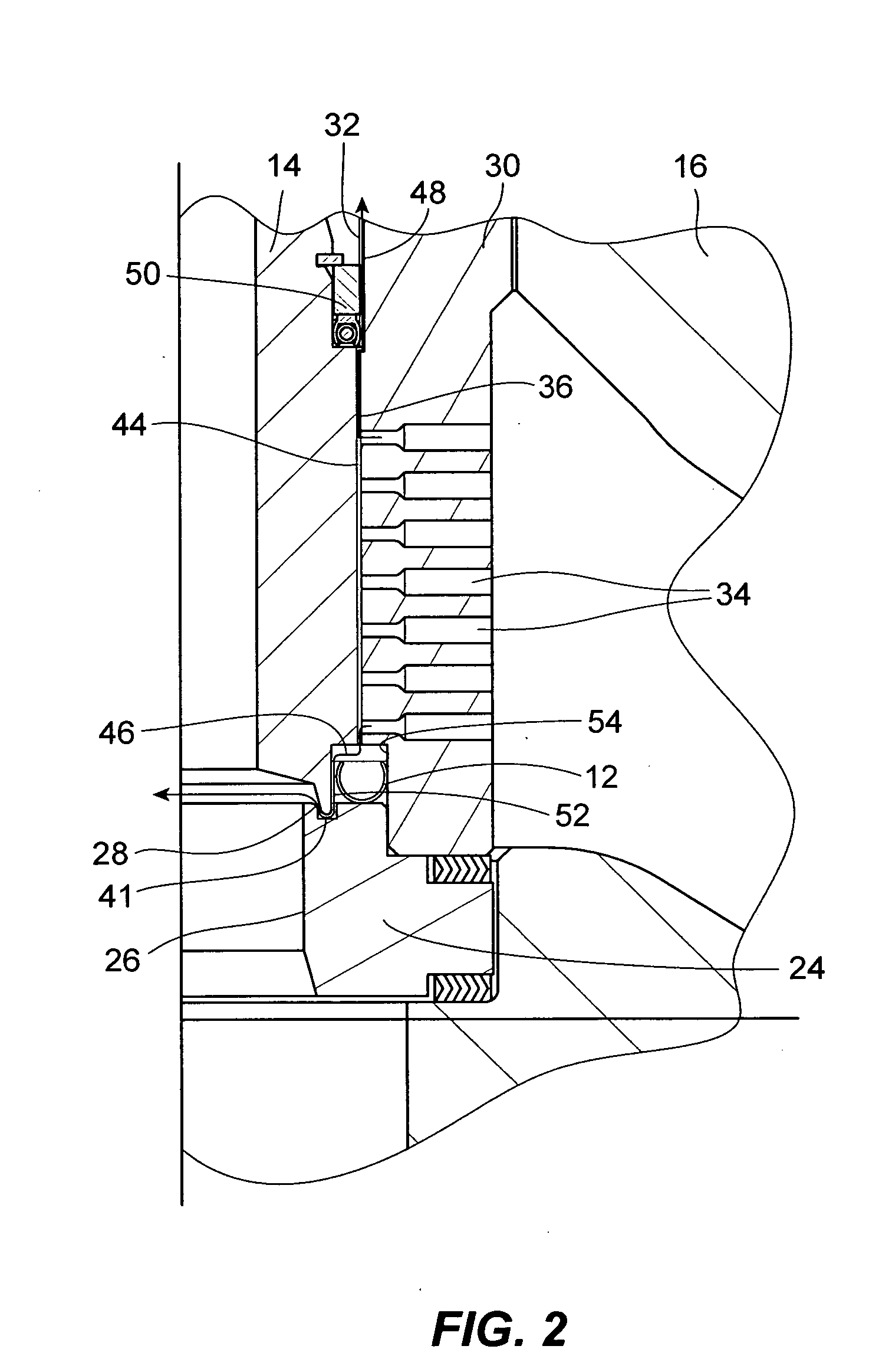
[0012] A seal for restricting fluid flow through a primary leak path is disclosed. The seal is disposed in the primary leak path and engages the throttling element in the closed position to reduce or prevent fluid flow through the leak path. The seal may replace or be provided in addition to conventional seals formed by the engagement of the throttling element with the valve seat ring, which are dependent on the actuator force applied to the throttling element. In one embodiment, the seal engages an inner perimeter of the throttling element thereby to locate the seal away from the normal fluid flow path when the throttling element is in the open position.
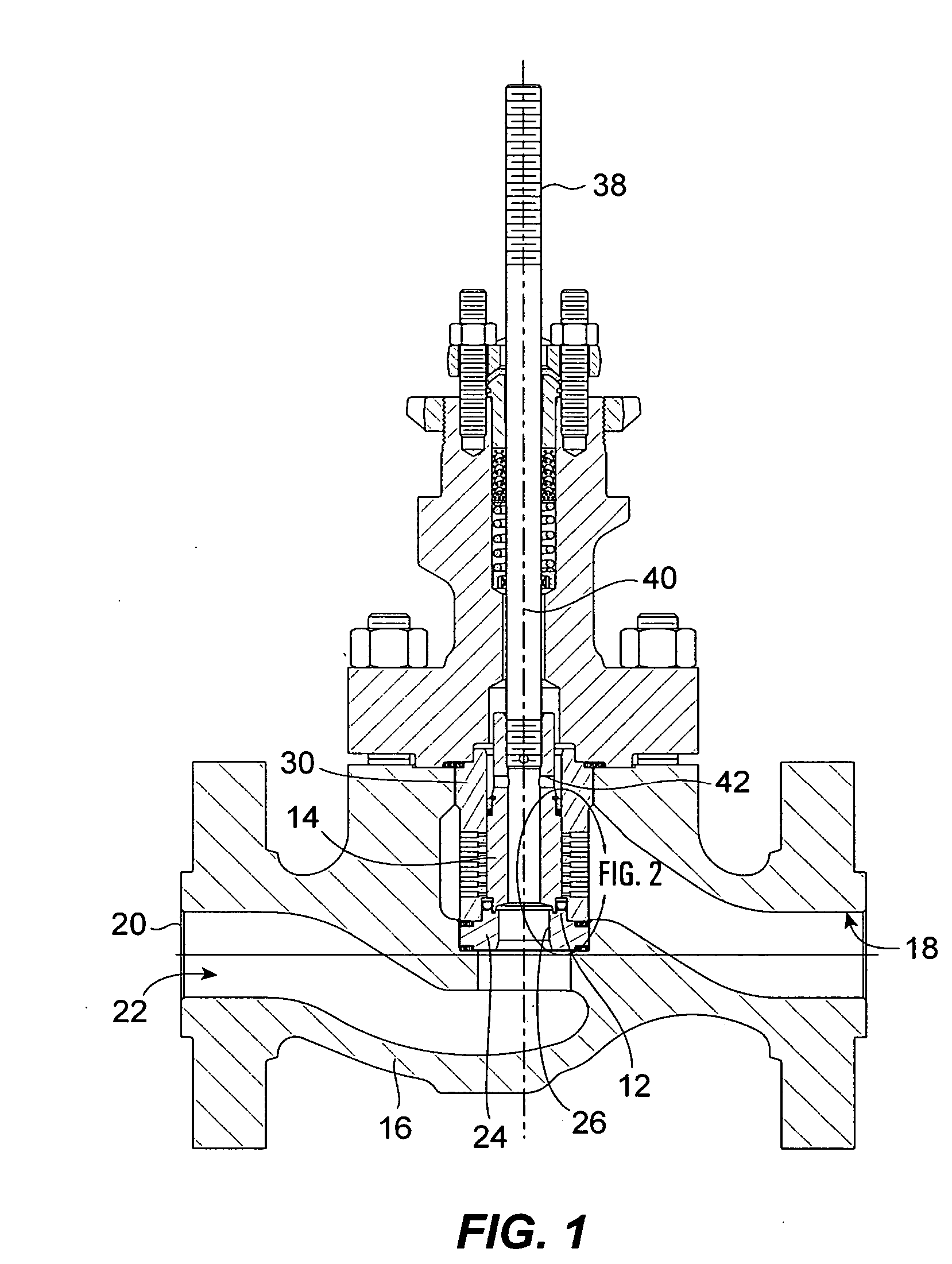
[0013]FIGS. 1 and 2 illustrate a first embodiment of a fluid flow control device in the form of a control valve 10 with a seal 12 engaging an outer perimeter of a throttling element 14. The control valve 10 includes a valve body 16 defining an inlet 18, an outlet 20, and fluid flow path 22 extending from the inlet to the outlet. A ...
PUM
 Abstract
Description
Claims
Application Information
 - Generate Ideas
- Intellectual Property
- Life Sciences
- Materials
- Tech Scout
- Unparalleled Data Quality
- Higher Quality Content
- 60% Fewer Hallucinations
Browse by: Latest US Patents, China's latest patents, Technical Efficacy Thesaurus, Application Domain, Technology Topic, Popular Technical Reports.
© 2025 PatSnap. All rights reserved.Legal|Privacy policy|Modern Slavery Act Transparency Statement|Sitemap|About US| Contact US: help@patsnap.com