Jacquard machine

a technology of jacquard and machine body, which is applied in the field of jacquard machines, can solve the problems of cost of gearboxes to drive the motion, cost of two-sided drive, and accessibility of jacquard

Inactive Publication Date: 2006-09-21
VAN DE WIELE MICHEL
View PDF18 Cites 5 Cited by
  • Summary
  • Abstract
  • Description
  • Claims
  • Application Information

AI Technical Summary

Benefits of technology

[0009] The purpose of the invention is to provide a Jacquard machine having a rigid construction and which may be used at high speeds whereas it will be possible to keep the price of the construction within limits.

Problems solved by technology

In the cost price of a Jacquard machine, the costs for gearboxes to drive the motion of these knife grids as well as the components extending across the width of the Jacquard machine (from left to right) are of great consequence.
This solution has the disadvantage that an expensive two-sided drive has to be provided.
This disadvantage is still of more consequence in case the ordinary crank mechanism should be replaced by a gearbox with cams.
Moreover the continuously rotating traversing shaft is situated below the knife grids, which is a disadvantage with respect to the accessibility of the Jacquard machine at the level of the selection system of the pulley system.
Thus the accessibility of the selection systems and the pulley systems indeed having been improved, but two gearboxes are still required and the installation of the gearboxes, crosswise in the centre, will give cause to the need of big, expensive, heavy and heavily loaded rocking levers which extend along almost the total depth (crosswise distance) of the Jacquard machine.
This embodiment is offering a solution to limit the drives to only one gearbox, but it is still provided with two traversing rocking shafts, which in itself is already an expensive solution and which moreover, additionally is made still heavier because of the coaxial design of both shafts.
Moreover, the levers, linked with these coaxial shafts are still extending almost along the total depth of the Jacquard machine, rendering the solution still more expensive and which has an increasing effect on the inertia.
With three traversing shafts, i.e. one continuously rotating shaft and 2 rocking shafts, this is not only an expensive solution, but also the accessibility is strongly restricted.
Also the design of the large and heavy rocking levers still remains an expensive solution which has an inertia increasing effect.

Method used


Image

  • Jacquard machine
  • Jacquard machine
  • Jacquard machine

Examples


Embodiment Construction

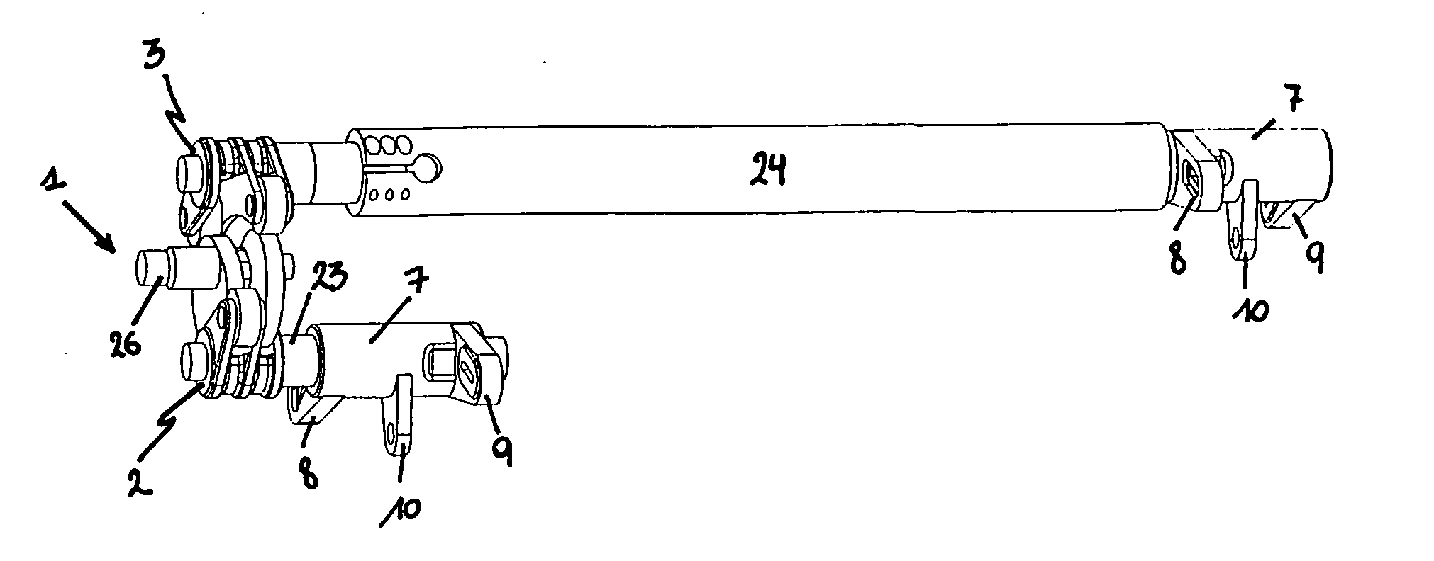
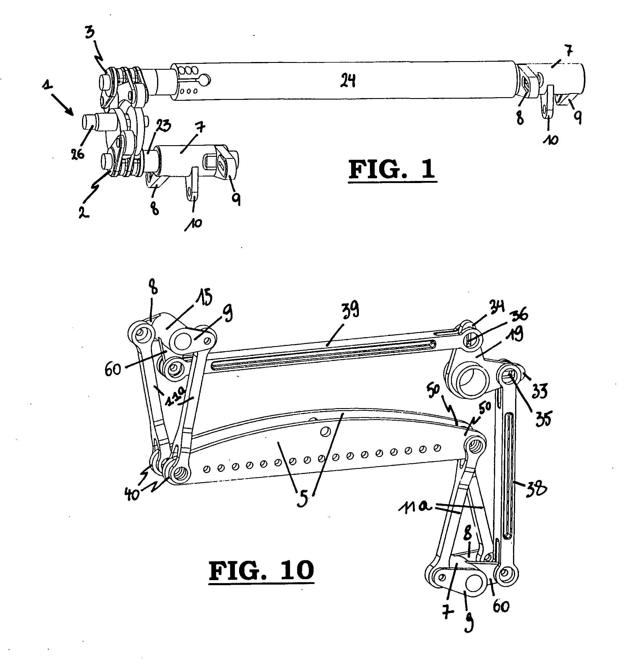
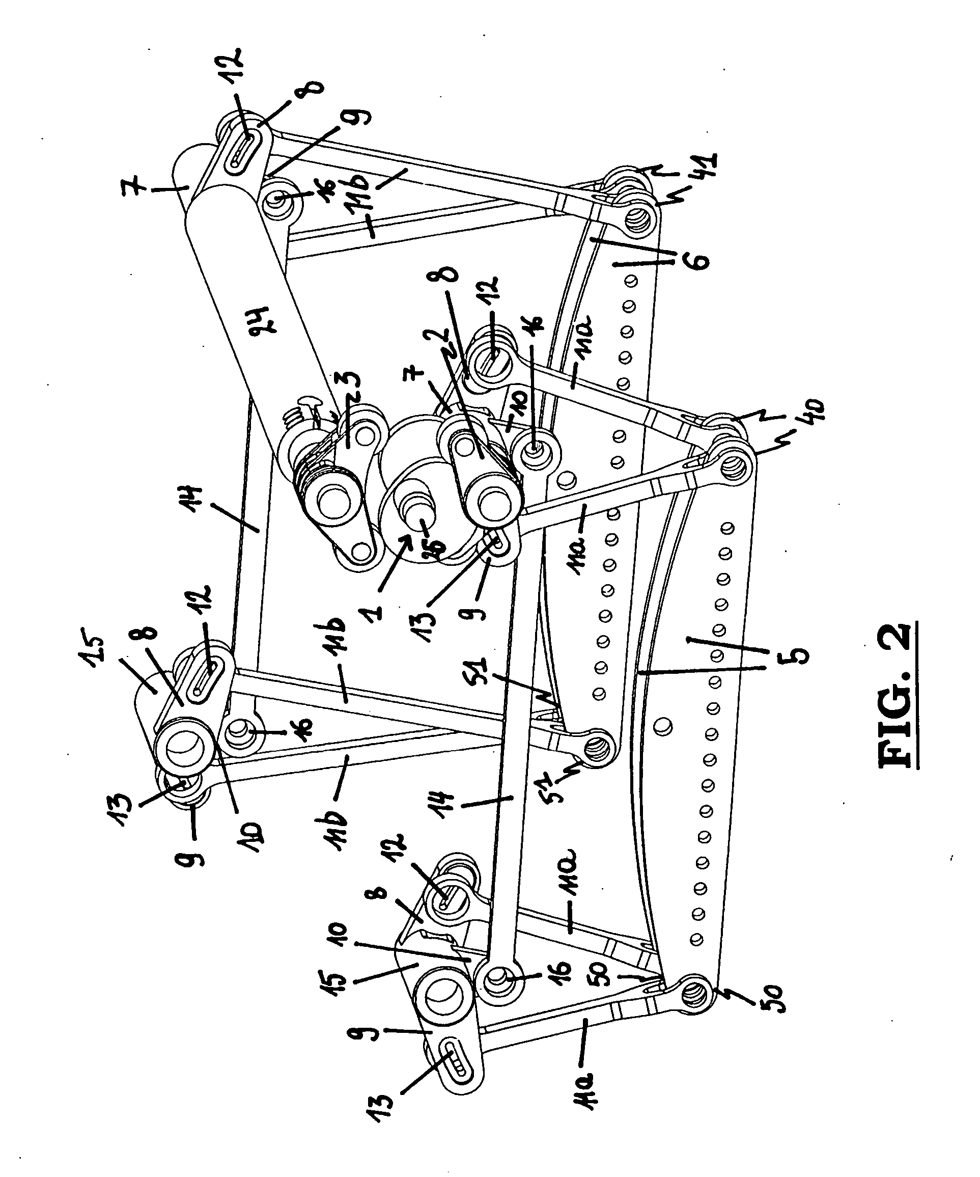
[0047] A Jacquard machine according to the invention, comprises at least 2 sets of knife grids (5, 6) moving up and down in opposition on either side of it (see FIGS. 2, 3, 7 up to and including 10). For driving the motion of the knife grids (5, 6) on either side of the Jacquard machine, at least one driving lever (2, 3, 10) is provided being driven by a single-sided drive (1) situated either on the left side or on the right side of the Jacquard machine and which may be installed crosswise in the front, at the back or in the middle (seen from the position of the weaver looking in the direction from where the warp arms are supplied). With a single-sided drive (1) it is possible to reduce the cost substantially, since the costs of an expensive doubled-sided drive according to the state-of-the-art are no longer to be paid. The double-sided drive being no longer required, the traversing continuously rotating shaft, as described according to the state-of-the-art, is no longer needed, how...


PUM


Abstract

The invention relates to a Jacquard machine, comprising at least two knife grids (5, 6) moving up and down in opposition on either side of the Jacquard machine, the Jacquard machine comprising a single-sided drive (1) for driving at least one driving lever (2,3) which is provided for driving the motion of the knife grids (5, 6) on either side of the Jacquard machine, and one traversing rocking shaft (24) being provided to transmit the motion of the said driving lever (2 and 3 respectively) to the knife grids (5, 6) of one of the sides of the Jacquard machine.

Description

[0001] This application claims the benefit of Belgian Application No. 2005 / 0150 filed Mar. 21, 2005, which is hereby incorporated by reference in its entirety. BACKGROUND OF THE INVENTION [0002] The invention relates to a Jacquard machine, comprising on either side of the Jacquard machine at least two knife grids moving up and down in opposition. [0003] The necessity to produce Jacquard machines operating at higher speeds at lower prices and, at the same time, sufficiently strong to be capable of forming the shed to suit the requirements in an accurate and reliable manner in order to realize a fabric of the quality desired, is putting an ever growing pressure on the construction of Jacquard machines. It is therefore important for the construction of Jacquard machines to make the knife drive, driving two sets of knives moving up and down in opposition, sufficiently rigid at a minimal cost. The two sets of knives moving up and down in opposition are taken up in a knife grid on either ...

Claims


Application Information

Patent Timeline
Patent Type & Authority Applications(United States)
IPC IPC(8): D03C3/00
CPCD03C3/36
Inventor VANDERJEUGT, BRAMTHEOBALD, MATTHEWGRAHAM, JAMES ANTHONY
Owner VAN DE WIELE MICHEL
Why Eureka
Try Eureka