Whipstock anchor

Active Publication Date: 2006-09-21
WEATHERFORD TECH HLDG LLC
View PDF14 Cites 45 Cited by
  • Summary
  • Abstract
  • Description
  • Claims
  • Application Information

AI Technical Summary

Benefits of technology

[0011] In another embodiment, an anchor for supporting a downhole tool in a wellbore comprises a first body and second body, the bodies slidably movable relative to each other to increase an outer diameter of the anchor in a set position; a biasing member disposed between the first body and the second body, the

Problems solved by technology

In these instances, the anchors can be set with pressurized fluid, but that requires a different apparatus and the type of anchor actually needed on a job is not always apparent in advance.
Because of the uncertainty of equipment needed to best form a window in a casing, there are instances in which the wrong type anchor is on site and delays are created as another more appropriate anchor is found.
An additional problem relates to the fact that most prior art anch

Method used


Image

  • Whipstock anchor
  • Whipstock anchor
  • Whipstock anchor

Examples


Embodiment Construction

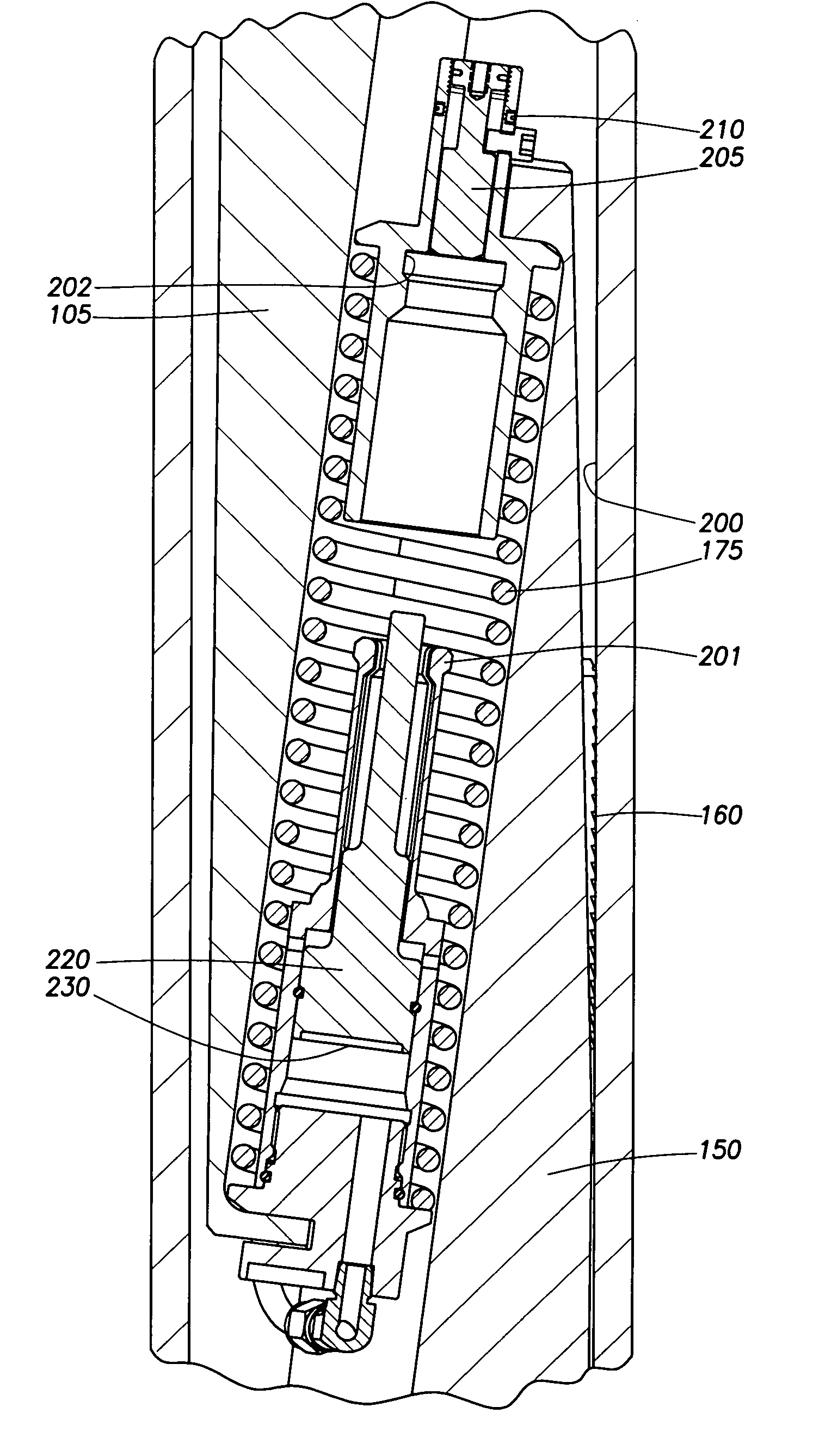
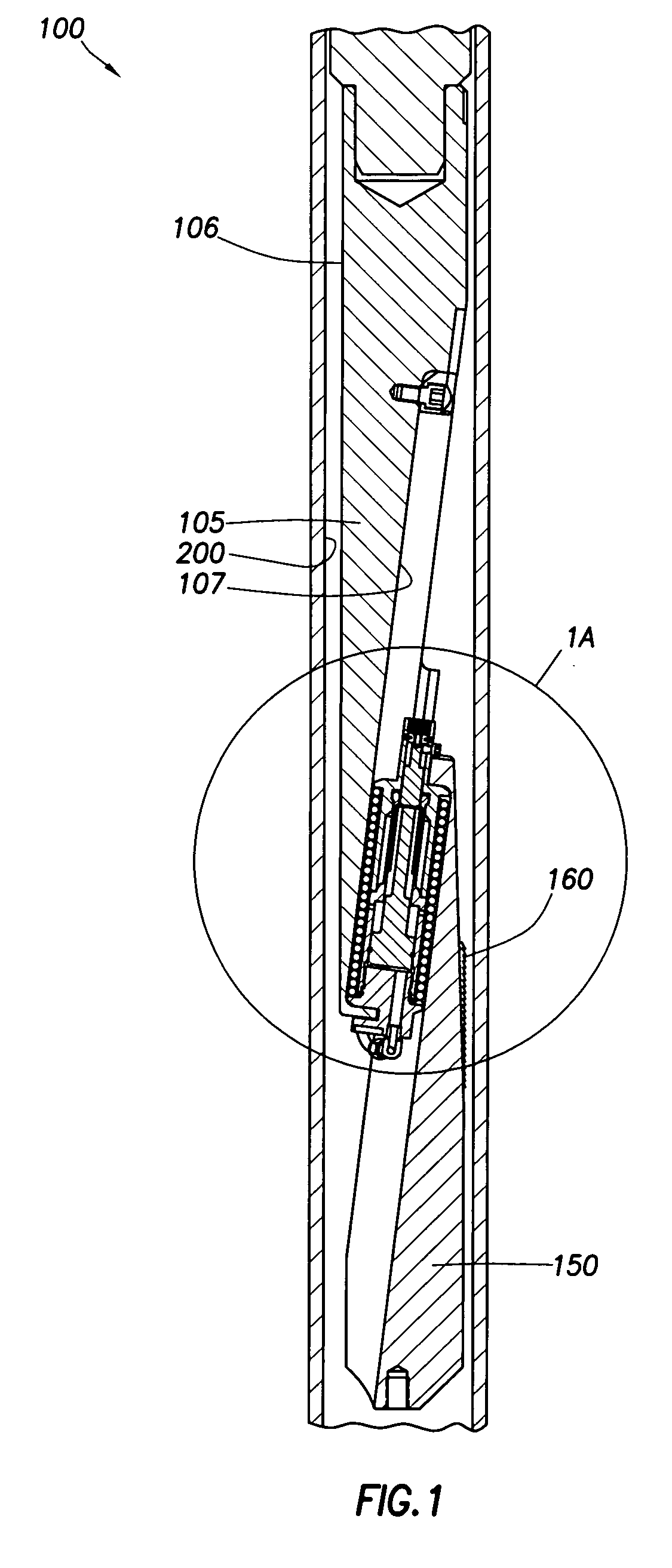
[0025]FIG. 1 is a side, section view of a hydraulic version of an anchor of the present invention, shown in a run-in position. The anchor 100 includes an anchor body 105 which is essentially a wedge-shaped, semicircular member with a first surface 106 substantially parallel to the inner wall 200 of surrounding casing and an inner surface 107 having sides that are gradually sloped. The anchor body 105 is connected to a whipstock which is not shown but is typically located directly above the anchor 100. A slip body 150 is somewhat of a mirror image of the anchor body 105 with inner and outer surfaces that are opposed to the surfaces of the anchor body 105. The slip body 150 typically includes at least one slip member 160 and is substantially free-floating relative to the anchor body 105.

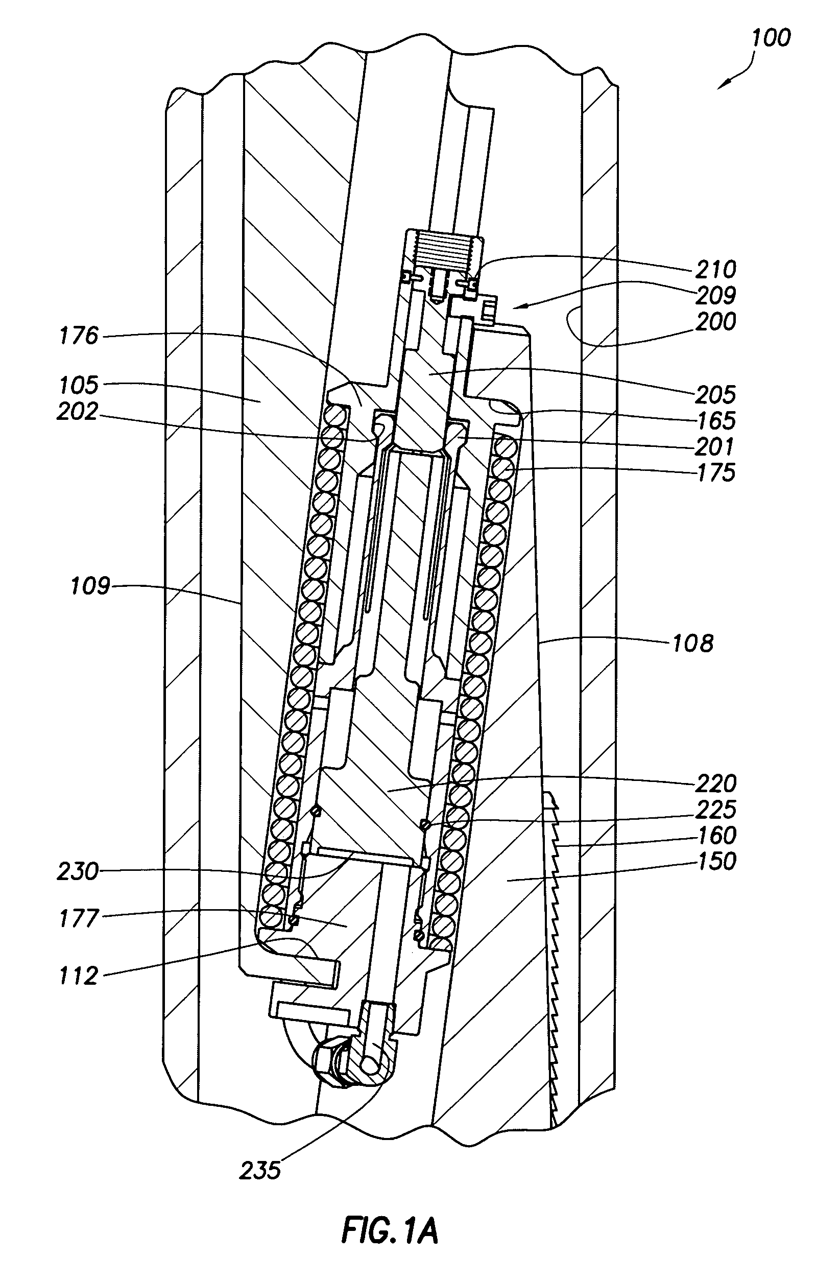
[0026]FIG. 1A is an enlarged view of the anchor 100 of FIG. 1. Due to a shoulder 165 formed at its upper end, the slip body 150 is movable relative to the anchor body 105 by a biasing member such as a...


PUM


Abstract

An anchor for a wellbore is adaptable to be operated in at least two separate and distinct ways. In one embodiment, a whipstock anchor is provided that can be operated either mechanically or hydraulically. In another embodiment, the anchor is designed to run through a restriction in a retracted position and thereafter expanded to position a wellbore tool in the wellbore. Preferably, the anchor is expandable to set in wellbores of various sizes and either cased or uncased.

Description

CROSS-REFERENCE TO RELATED APPLICATIONS [0001] This application claims benefit of co-pending U.S. Provisional Patent Application Ser. No. 60 / 658,506, filed on Mar. 4, 2005, which application is incorporated herein by reference in its entirety.BACKGROUND OF THE INVENTION [0002] 1. Field of the Invention [0003] The present invention relates to a downhole tool. More particularly, the invention relates to a downhole tool that can be actuated in multiple, separate ways. More particularly still, the invention relates to a downhole anchor that can be set either mechanically or hydraulically in casing of a variety of sizes and weights. [0004] 2. Description of the Related Art [0005] When oil and gas wells are drilled, a bore hole is formed in the earth and typically lined with steel pipe that is cemented into place to prevent cave in and to facilitate the isolation of certain areas of the wellbore for the collection of hydrocarbons. Once the steel pipe or casing is cemented into place, the ...

Claims


Application Information

Patent Timeline
IPC IPC(8): E21B23/00
CPCE21B7/061E21B23/01
Inventor RIOS, ARISTEO IIIMARSHALL, GREGHESTER, STEPHEN HERMESVUYK, ADRIAN JR.WINTERROWD, KEN W.BLANKENSHIP, DAN
Owner WEATHERFORD TECH HLDG LLC
Why Eureka
Try Eureka