Technique for drilling straight bore holes in the earth

a technology of straight bore holes and earth, which is applied in the direction of drilling pipes, drilling casings, directional drilling, etc., can solve the problems of large equipment, prohibitively expensive, and over-difficulty in making long stabilizers with integral stabilizing sections, and achieves small eccentric motion, good balance, and small lateral forces

Inactive Publication Date: 2006-09-21
CLAYTON TROY LEE
View PDF20 Cites 23 Cited by
  • Summary
  • Abstract
  • Description
  • Claims
  • Application Information

AI Technical Summary

Benefits of technology

[0006] The stabilizer is balanced mainly by making the inner and outer diameters very concentric to the tube centerline. This is accomplished by providing a cylindrical axial passage that is on the centerline of the tube, subject to very close tolerances, and a cylindrical exterior surface between the stabilizing sections that has been ground or machined to be concentric, subject to very close tolerances, to the tube centerline. Because of the small tolerances of the interior and exterior of the stabilizer, the wall thickness of the stabilizer is very consistent so the stabilizer is very well balanced, meaning there is very little whip or eccentricity during rotation.

Problems solved by technology

It is exceedingly difficult to make a long stabilizer with integral stabilizing sections to very close tolerances.
The reason is that the grinding machines used to dress the external diameter have 8½′ centers, meaning that longer stock cannot be chucked into the machine.
Such equipment is massive, prohibitively expensive when new, and awkward to ship and install.

Method used


Image

  • Technique for drilling straight bore holes in the earth
  • Technique for drilling straight bore holes in the earth

Examples


Embodiment Construction

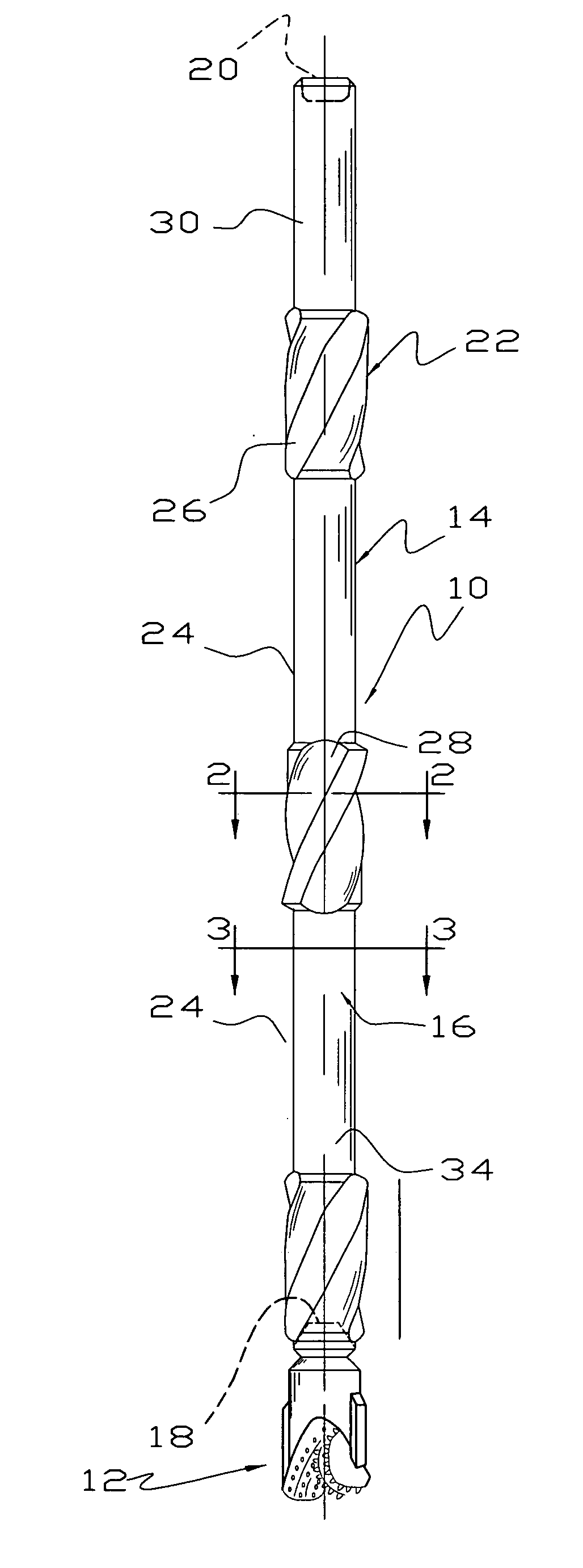
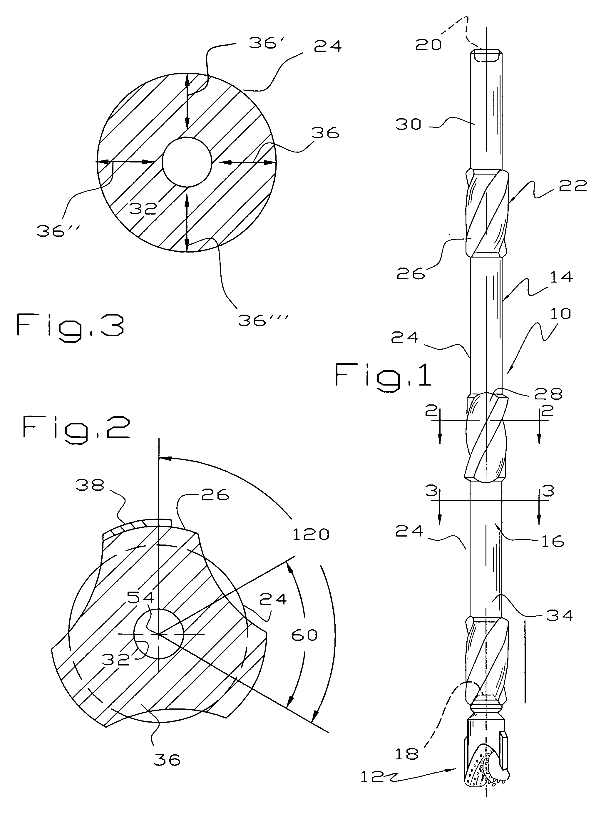
[0017] Referring to FIGS. 1-3, there is illustrated a drilling assembly 10 comprising a bit 12 and a bottom hole or stabilizer assembly 14. The bit 12 may be of any suitable type such as a cone-roller bearing type, a conventional diamond bit or a polycrystalline insert type. The stabilizer assembly 14 is made of one piece of metal and comprises a central tube 16 having a threaded female connection or box 18 at one end into which the bit 12 is threaded and another threaded female connection or box 20 at the other end for connection to a drill collar joint (not shown), another stabilizer (not shown) or other oil field tubular. At least three stabilizer sections 22 are located on the exterior of the tube 16 and are separated by cylindrical sections 24. The stabilizer sections 22 are of a larger outer diameter than the tube 16 and preferably provide helical ribs 26 and flutes 28 for swirling drilling mud as it passes upwardly away from the bit 12. A fishing neck 30 at the upper end of t...


PUM


Abstract

A stabilizer assembly is at least 12′ long and preferably at least 14′ long and is used to drill a straight bore hole in the earth. A central passage through the assembly closely follows a centerline as may be determined by measuring the wall thickness of the tube at a variety of locations in a single plane. At least three stabilizing sections are integral with the tube and include alternating ribs and flutes. Hardbanding on the ribs is ground down to tolerances with a grinding machine or face plate lathe having centers sufficient to receive the 12′ long stabilizer assembly.

Description

[0001] This invention relates to a technique for drilling straight bore holes in the earth and more particularly to a stabilizer assembly and a method of making and using the same. BACKGROUND OF THE INVENTION [0002] As discussed at some length in U.S. Pat. No. 4,874,045, the art of drilling bore holes in the earth has evolved substantially. Initially, a bit was simply threaded onto the end of drill pipe and the resultant bore hole meandered significantly into the earth, typically in a corkscrew manner. At the present time, an attempt to drill a relatively straight vertical bore hole in the earth incorporates an elaborate bottom hole assembly including a series of stabilizers above the bit and a long length of drill collars above and interspersed between stabilizers. [0003] It has become more desirable to drill straight vertical bore holes in the earth as wells are being drilled deeper. This is because of increased friction generated between rotating drill pipe and the bore hole. One...

Claims


Application Information

Patent Timeline
Patent Type & Authority Applications(United States)
IPC IPC(8): E21B17/10
CPCE21B7/04E21B17/1078E21B17/22
Inventor CLAYTON, CHARLEY H.
Owner CLAYTON TROY LEE
Why Eureka
Try Eureka