
Seatbelt retractor system and seatbelt system

Inactive Publication Date: 2006-09-21
JOYSON SAFETY SYST JAPAN KK
View PDF7 Cites 13 Cited by
  • Summary
  • Abstract
  • Description
  • Claims
  • Application Information

AI Technical Summary

Benefits of technology

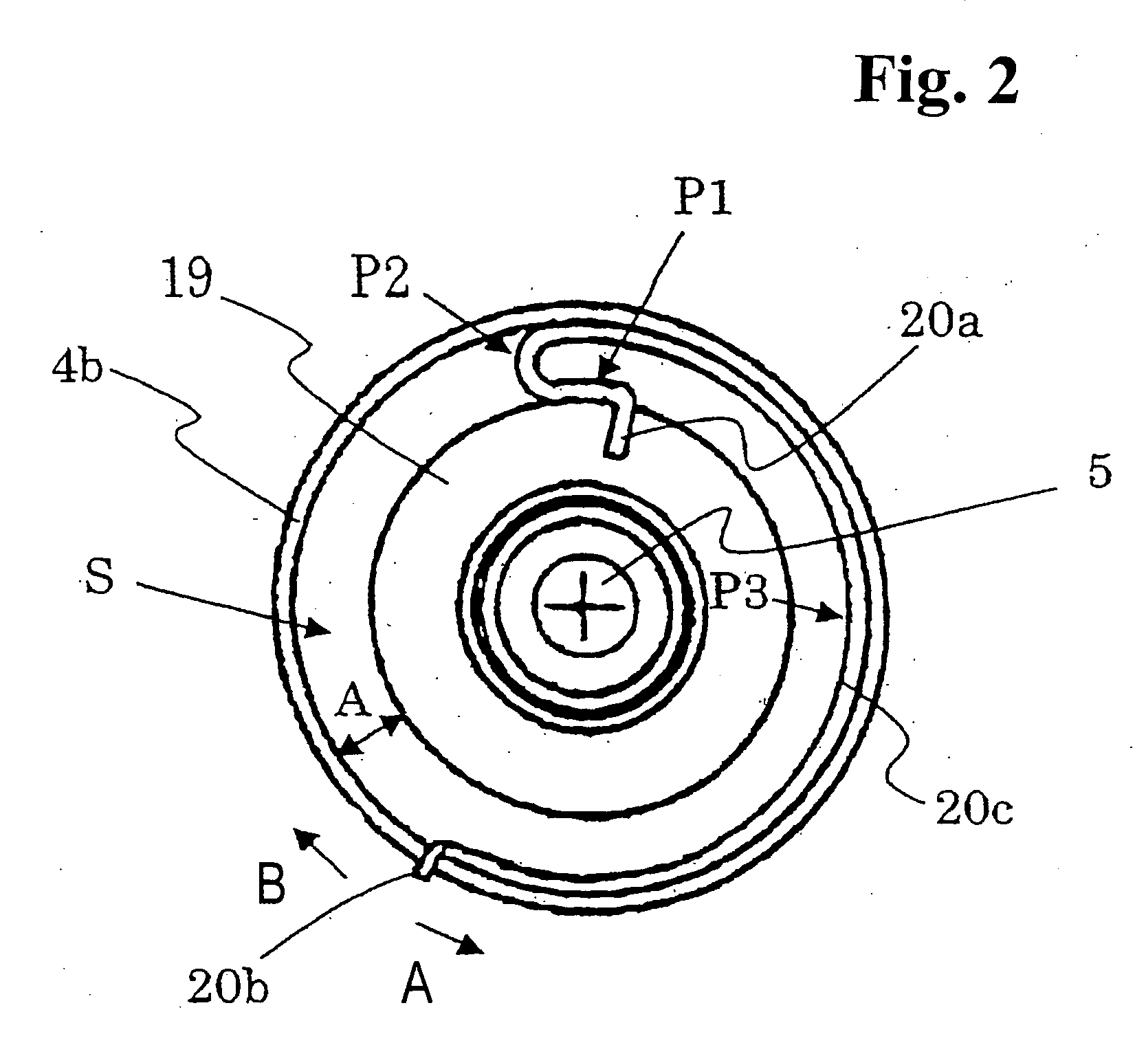
[0015] At that time, the amount of the energy absorbing load and the energy absorbing region can be varied by changing the material, thickness and so on of the shaft member. Particularly, for the energy absorbing member, the amount of the energy absorbing load and the energy absorbing region can be varied more easily. Specifically speaking, (a) the load can be decreased (or increased) by increasing (or decreasing) the radial length of a ring-shaped space formed between the outer periphery of the mounting member and the inner periphery of the axial end of the substantially cylindrical member. (b) The load can be increased (or decreased) by increasing (or decreasing) the thickness of the energy absorbing member. (c) The load characteristics can be changed by circumferentially changing the engaging position for the second end of the energy absorbing member in the inner periphery of the axial end of the substantially cylindrical member to thereby vary the relative rotation stroke characteristic during the winding.
[0034] According to the disclosed aspects, the energy absorbing characteristics of the entire retractor system can easily be varied. This arrangement facilitates optimization of the energy absorbing characteristics according to the difference in vehicle structure in response to recent needs, thus protecting the body of an occupant sufficiently. The use of the energy absorbing member having a substantially circular cross section eliminates the need for increasing the thickness of the mounting member, thus providing a compact system.

Problems solved by technology

Here, it is difficult for the known structure having the EA plate between the inner periphery of the spool and the outer periphery of the shaft to change the load on the EA plate by the above-describe methods.

Method used


Image

  • Seatbelt retractor system and seatbelt system
  • Seatbelt retractor system and seatbelt system
  • Seatbelt retractor system and seatbelt system

Examples


Embodiment Construction

[0049] Embodiments of the present invention will be described with reference to the drawings.

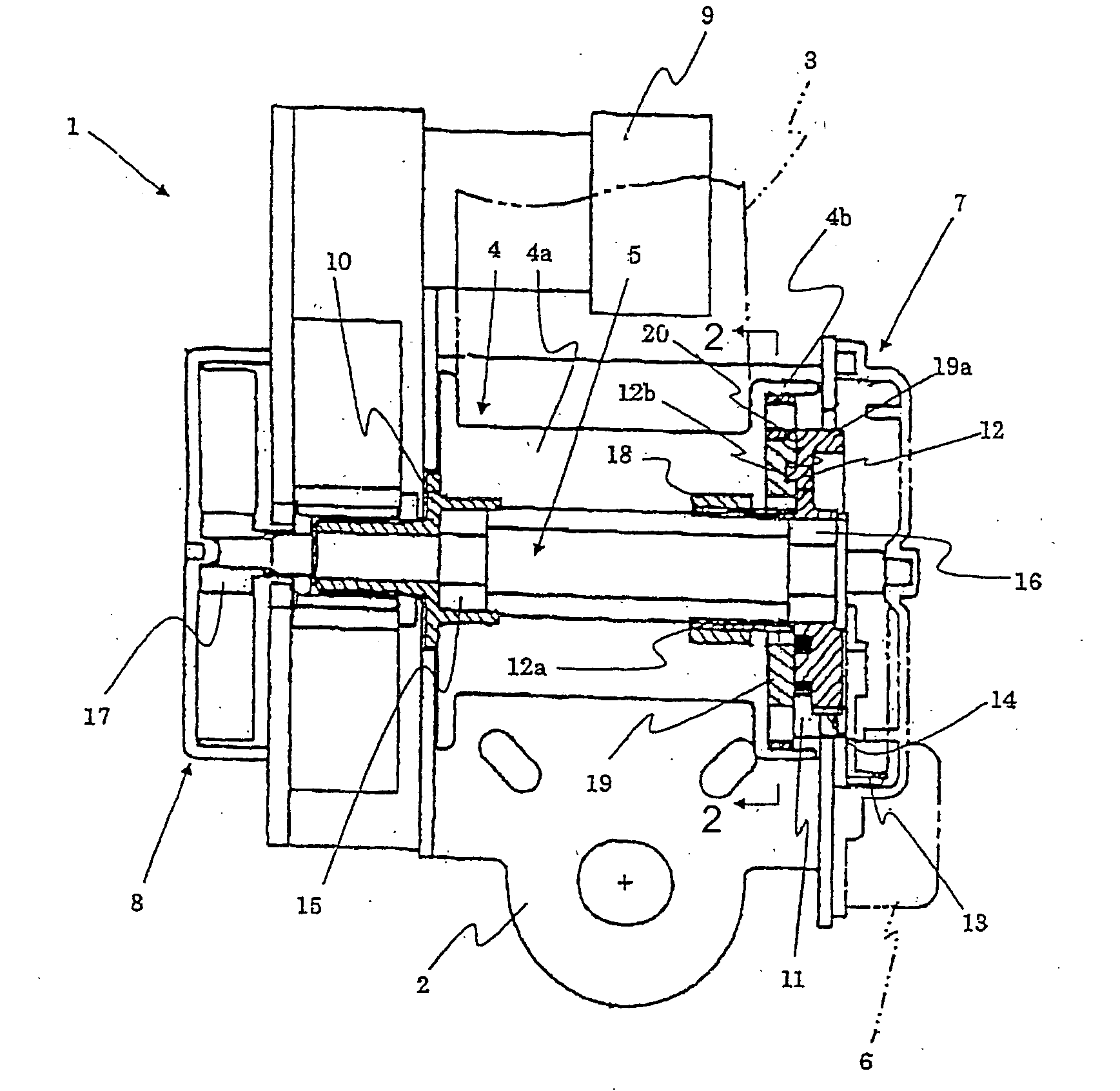
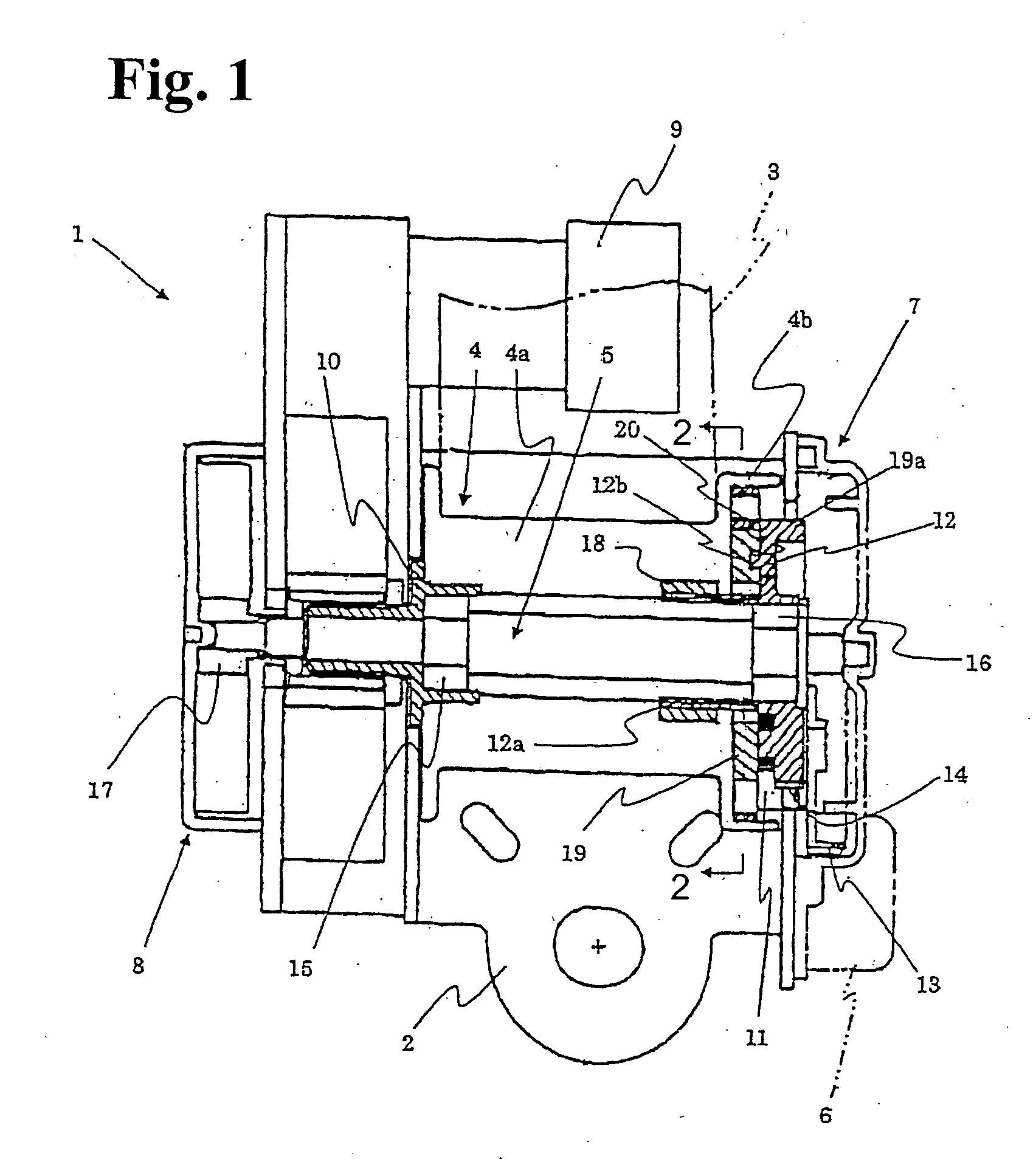
[0050]FIG. 1 is a schematic longitudinal sectional view of the entire structure of a seatbelt retractor system according to the embodiment.

[0051] Referring to FIG. 1, the retractor system 1 includes a frame 2; a spool (substantially cylindrical member) 4 for retracting a seatbelt 3; a torsion bar 5 (shaft member) made of a twistable material; a deceleration sensing means 6 that is activated by sensing a large vehicle deceleration generated in an emergency; a locking mechanism 7 that stops the rotation of the spool 4 at least in a belt withdrawing direction; a spring means 8 having a spiral spring (not shown); a pretensioner 9 that is activated in an emergency to generate a belt retracting torque; and a bush 10 that transmits the seatbelt retracting torque of the pretensioner 9 to the spool 4.

[0052] The locking mechanism 7 includes a locking base 12 that holds a pawl 11 in such a manner as...


PUM


Abstract

A seatbelt retractor system allowing optimization of energy absorbing characteristics, includes a spool for retracting a seatbelt; a torsion bar made of a twistable material; a locking mechanism for stopping the rotation of the spool at least in a seatbelt withdrawing direction; a substantially disk shaped ring disposed in the inner periphery of an axial end of the spool; and a plastically deformable energy absorbing member. The energy absorbing member may have a substantially circular cross section. A first end of the energy absorbing member may be fixed to an outer periphery of the substantially disc-shaped ring, while a second end of the energy absorbing member may be detachably engaged with an inner periphery of the spool.

Description

CROSS-REFERENCE TO RELATED APPLICATION [0001] This is a continuation in part application of Ser. No. 10 / 815,935 filed on Apr. 2, 2004.BACKGROUND OF THE INVENTION AND RELATED ART STATEMENT [0002] The present invention relates to a seatbelt retractor system for retracting the webbing of a seatbelt and, more particularly, it relates to a seatbelt retractor system having an energy absorption mechanism (an EA mechanism) for absorbing an inertial energy applied to an occupant when restraining the movement of the occupant by locking the seatbelt in an emergency to a seatbelt system. [0003] Seatbelt systems provided to vehicle seats are essential systems for ensuring the safety of occupant's bodies by restraining abrupt movement of the occupants due to acceleration generated at vehicle collision. [0004] The seatbelt systems generally include a webbing (belt), a retractor system, a buckle unit and the like. [0005] The retractor system winds the webbing around a winder (a bobbin or a spool) t...

Claims


Application Information

Patent Timeline
IPC IPC(8): B60R22/36
CPCB60R21/16B60R22/3413B60R22/4676B60R2022/286B60R2022/287
Inventor HIRAMATSU, KOJI
Owner JOYSON SAFETY SYST JAPAN KK
Learn More