Cooled furnace wall

a furnace wall and furnace technology, applied in furnaces, manufacturing converters, lighting and heating apparatus, etc., can solve the problems of relatively high pressure loss in the transition region between the connection piece and the cooling passage, and the production cost of the cooling plate is higher, so as to achieve significant time savings, reduce pressure loss, and prolong service life

Inactive Publication Date: 2006-09-21
PAUL WURTH SA
View PDF4 Cites 15 Cited by
  • Summary
  • Abstract
  • Description
  • Claims
  • Application Information

AI Technical Summary

Benefits of technology

[0013] In accordance with the present invention, the tube bend connection pieces of two adjacent cooling plates connected in series may lie relatively close together. This is of advantage with regard to the arrangement of the connection openings in the furnace shell and the interconnection of the connection pieces.
[0014] The tube bend connection pieces of two cooling plates are preferably connected by means of flexible connection means. In accordance with another aspect of the present invention, these flexible connection means are accommodated in a sealed connection box which is arranged on the outer side of the furnace shell and is preferably closed off by means of a removable blind flange. This eliminates the need for expensive, sealed tube passages through the furnace shell and results in significant time savings when mounting the cooling plates. Furthermore, it will be appreciated that a connection box of this type may also be dimensioned in such a manner that a cooling plate can be rem...

Problems solved by technology

However, compared to cooling plates with cast-in cooling tubes or compared to mould-cast cooling plates, the finished cooling plates produced by both processes have the drawback of relatively high pressure l...

Method used


Image

  • Cooled furnace wall
  • Cooled furnace wall
  • Cooled furnace wall

Examples


Embodiment Construction

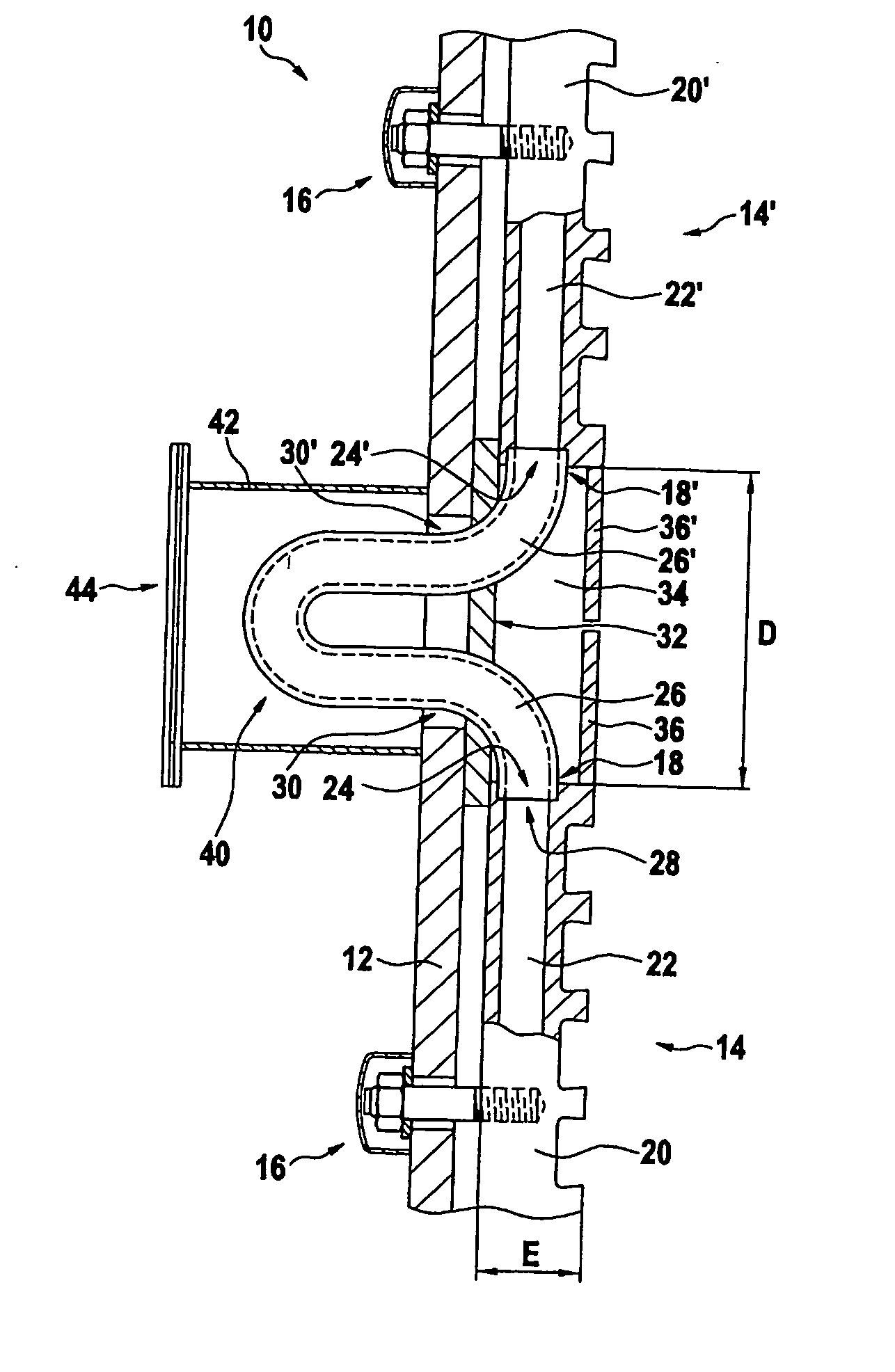
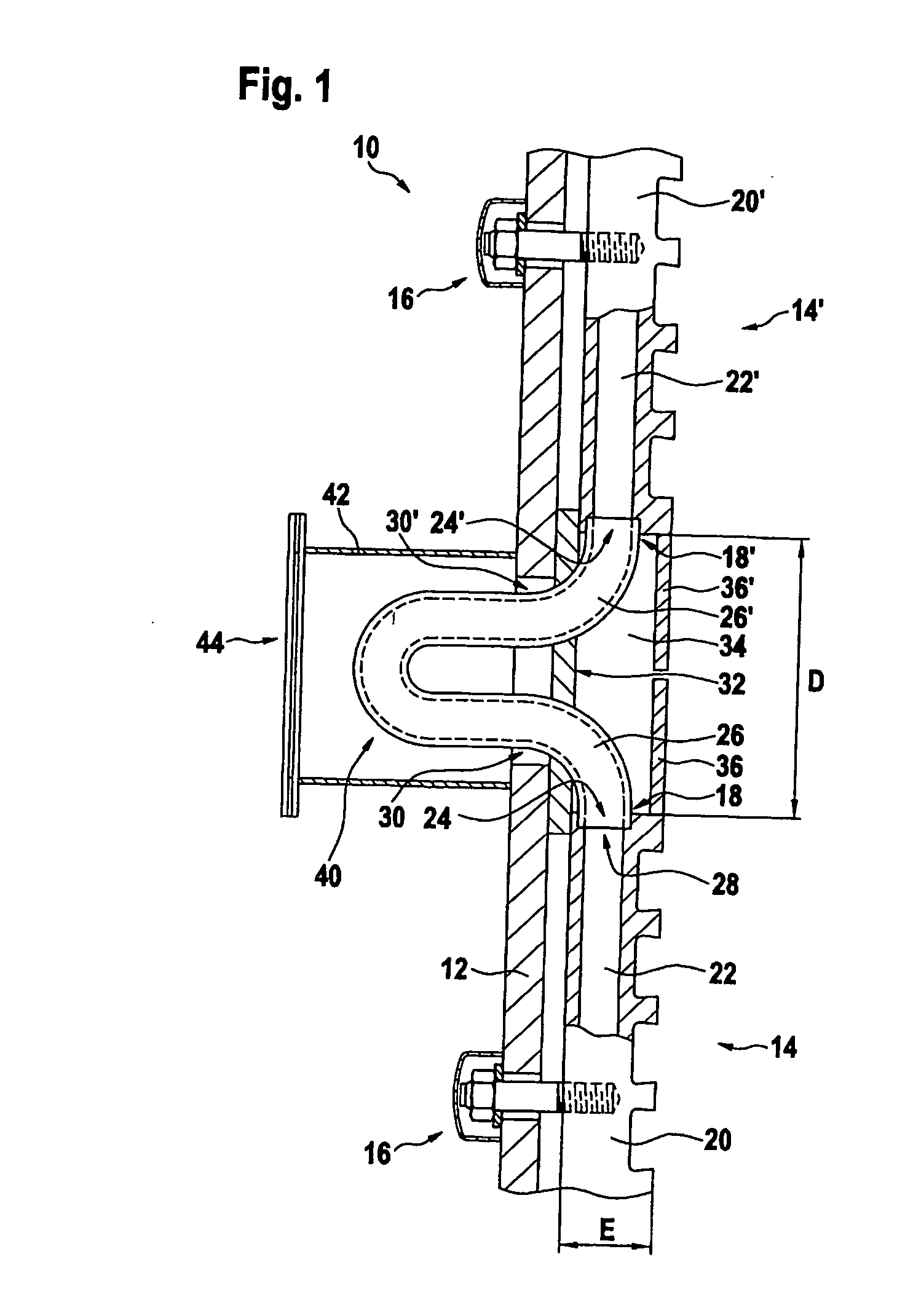
[0042] The furnace wall 10 shown in the drawings to illustrate the invention is a blast furnace wall cooled by means of cooling plates. In FIGS. 1 and 2, reference numeral 12 denotes a furnace shell. An upper end of a lower cooling plate 14 and a lower end of an upper cooling plate 14′ can be seen on the inner side of the furnace shell 12. These cooling plates 14, 14′ are affixed to the furnace shell 12 by means of threaded bolts 16 and form a cooled lining of the inner side of the furnace shell 12. “D” denotes the vertical distance between the upper edge face 18 of the lower cooling plate 14 and the lower edge face 18′ of the upper cooling plate 14′. In the embodiments shown in FIG. 1 and FIG. 2, this distance “D” approximately corresponds to three times the thickness “E” of the cooling plates 14, 14′.

[0043] The cooling plates 14, 14′ shown in FIG. 1 and FIG. 2 have a solid cooling plate body 20, 20′ made from copper or a copper alloy. Vertical cooling passages 22, 22′ are arrange...


PUM

PropertyMeasurementUnit
Angleaaaaaaaaaa
Angleaaaaaaaaaa
Angleaaaaaaaaaa

Abstract

A cooled furnace wall comprises a furnace shell with an inner and an outer side and cooling plates lining the inner side of the furnace shell. Each of the cooling plates has a plate body and protruding connection pieces for supplying the cooling plate with a coolant. The furnace shell has connection openings therein for interconnecting the connection pieces of adjacent connection plates from the outer side of the furnace shell. At least one of the connection pieces is formed by a tube bend that protrudes from an edge face of the plate body and that has a connection end to extending through one of the connection openings in the furnace shell.

Description

TECHNICAL FIELD [0001] The present invention generally relates to a cooled furnace wall. It relates more particularly to a furnace wall comprising a furnace shell with an inner side and an outer side and cooling plates lining the inner side of the furnace shell. Each of these cooling plates has a plate body with protruding connection pieces for a coolant. The furnace shell has connection openings therein, which enable to interconnect the protruding connection pieces of adjacent cooling plates from the outer side of the furnace shell. BACKGROUND ART [0002] It is well known to line the inner side of a furnace shell of a metallurgical furnace, in particular a blast furnace, with cooling plates. Such a cooling plate, also called “stave”, comprises a rectangular, solid plate body with cooling passages therein. Connection pieces, which protrude from the rear side of the cooling plate, debouch into the cooling passages of the cooling plate. These connection pieces are led in a sealed manne...

Claims


Application Information

Patent Timeline
IPC IPC(8): C21B7/06C21C5/44C21B7/10F27B1/12F27B1/24F27D9/00F28F9/26
CPCC21B7/10F27B1/12F27B1/24F27D9/00F27D2009/0013F27D2009/0048F27D2009/0051F27D2009/0062F28D2021/0078F28F9/26
Inventor SCHMELER, ROBERT
Owner PAUL WURTH SA
Why Eureka
Try Eureka