
Plasma display panel

a technology of display panel and plasma, which is applied in the direction of address electrodes, static indicating devices, instruments, etc., can solve the problems of significant damage to the electrodes, and achieve the effect of improving contrast and reducing the reflection of external objects

Inactive Publication Date: 2006-09-21
SAMSUNG SDI CO LTD
View PDF10 Cites 9 Cited by
  • Summary
  • Abstract
  • Description
  • Claims
  • Application Information

AI Technical Summary

Benefits of technology

[0017] The present invention has been developed in an effort to provide a plasma display panel having the advantage of easily reducing the reflection of external light without a great change in the manufacturing process, thereby improving contrast.

Problems solved by technology

In the DC type PDP, charge is directly transferred between corresponding electrodes, and accordingly there is a problem in that the electrodes are significantly damaged.

Method used


Image

  • Plasma display panel
  • Plasma display panel
  • Plasma display panel

Examples


Embodiment Construction

[0039] An embodiment of the present invention will hereinafter be described in detail with reference to the accompanying drawings. The present invention may, however, be embodied in different forms and should not be construed as limited to the exemplary embodiment set forth herein.

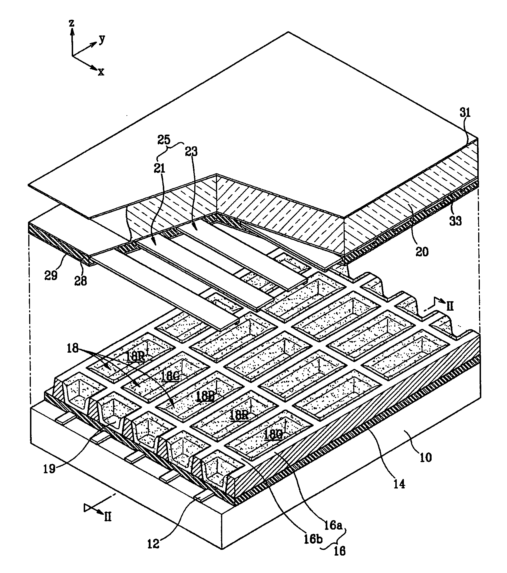
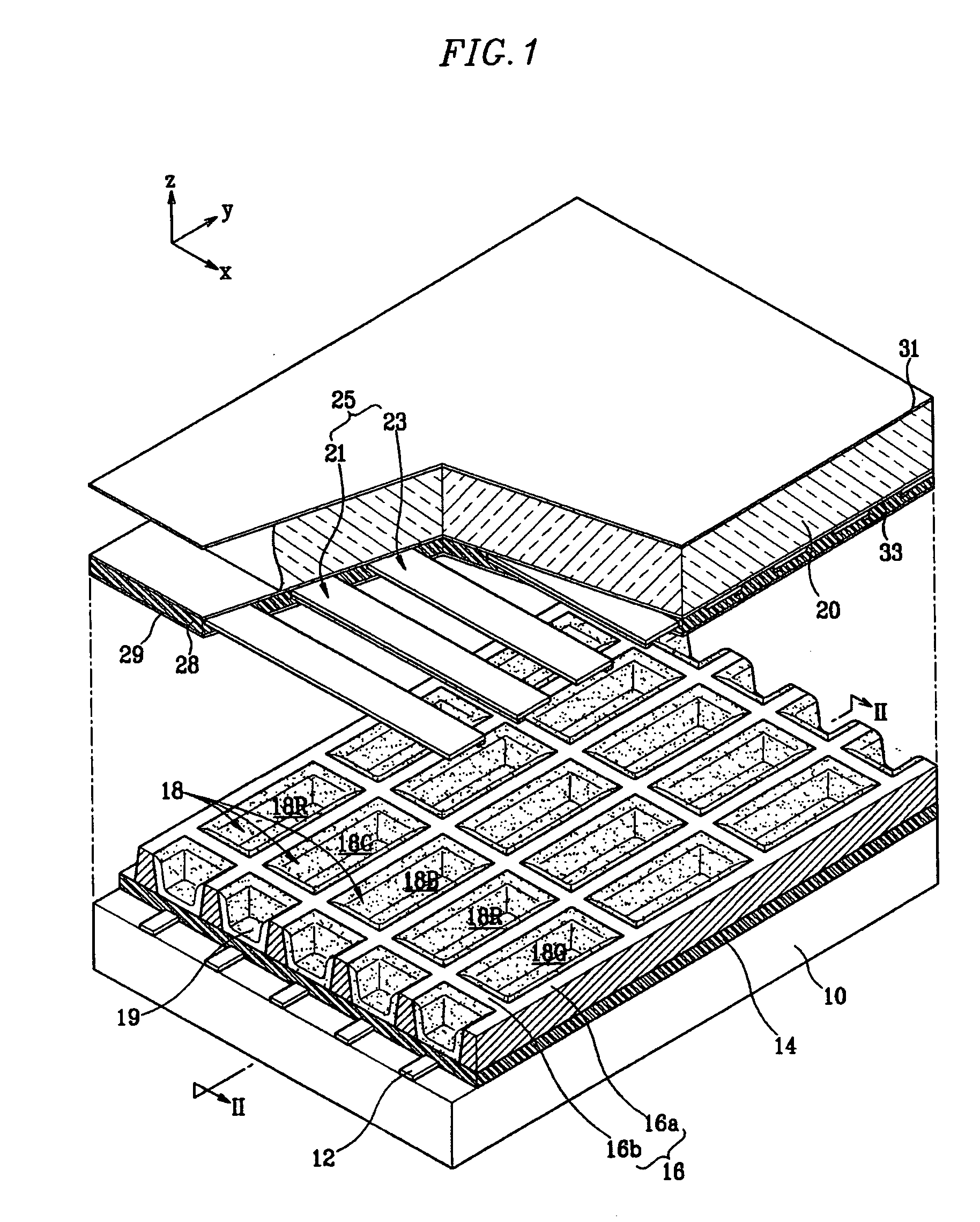
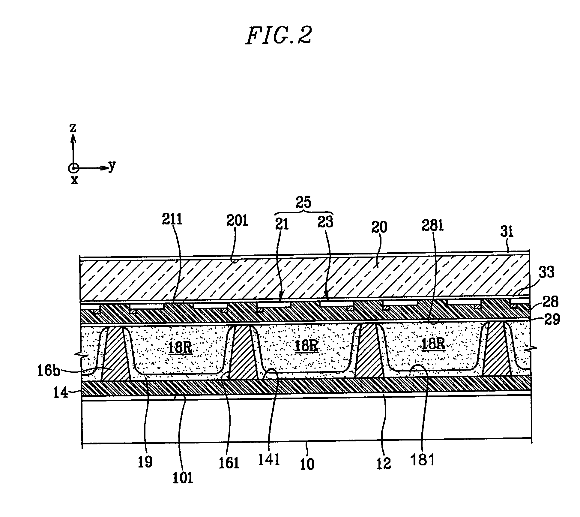
[0040]FIG. 1 is an exploded perspective view showing a plasma display panel (PDP) according to a first exemplary embodiment of the present invention, and FIG. 2 is a partially cross-sectional view taken along the line II-II of FIG. 1.

[0041] Referring to FIGS. 1 and 2, in the PDP of the first exemplary embodiment, a rear substrate 10 and a front substrate 20 are arranged so as to be spaced apart from and facing each other. Color-based discharge cells 18 (18R, 18G, and 18B) are partitioned using barrier ribs 16 in a space between the rear substrate I0 and front substrate 20. Furthermore, a phosphor layer 19 is formed in each discharge cell 18. In more detail, the phosphor layer 19 is formed on side surface...


PUM


Abstract

A plasma display panel (PDP) includes front and rear substrates arranged so as to face each other, first and second complementary color films arranged so as to be parallel with the front and rear substrates, barrier ribs for partitioning a plurality of discharge cells at a space between the front and rear substrates, an address electrode formed and extending along one direction so as to correspond to each discharge cell, a phosphor layer formed within the discharge cell, a display electrode, and a dielectric layer covering the display electrode. The first and second complementary color films have colors which have a mutually complementary color relationship. The display electrode corresponds to each discharge cell, and extends in a direction intersecting the direction of the address electrode.

Description

CLAIM OF PRIORITY [0001] This application makes reference to, incorporates the same herein, and claims all benefits accruing under 35 U.S.C. §119 from an application for PLASMA DISPLAY PANEL, earlier filed in the Korean Intellectual Property Office on the 17th Mar. 2005 and there, duly assigned Serial No. 10-2005-0022206. BACKGROUND OF THE INVENTION [0002] 1. Technical Field [0003] The present invention relates to a plasma display panel, and more particularly to a plasma display panel for reducing reflection of external light, thereby improving contrast. [0004] 2. Related Art [0005] In recent years, apparatuses using the plasma display panel (hereinafter, referred to as “PDP”) has been highlighted as the next generation of large-sized flat displays. Such PDPs is have excellent characteristics of a large screen, high definition, ultra-thinness, light weight, and wide viewing angle. Furthermore, PDPs are simply manufactured and are easier to produce as a large screen in comparison to ...

Claims


Application Information

Patent Timeline
IPC IPC(8): G09G3/28H01J61/00H01J11/12H01J11/22H01J11/24H01J11/26H01J11/34H01J11/36H01J11/38H01J11/40H01J11/42H01J11/44H01J11/50
CPCH01J11/12H01J11/44H01J2211/444A01K55/00A01K51/00
Inventor KWEON, TAE-JOUNG
Owner SAMSUNG SDI CO LTD
Learn More