Silicon-made magnetic head slider and method of producing the same

Inactive Publication Date: 2006-09-21
WESTERN DIGITAL TECH INC
View PDF16 Cites 5 Cited by
  • Summary
  • Abstract
  • Description
  • Claims
  • Application Information

AI Technical Summary

Benefits of technology

[0025] According to a magnetic disk device, a magnetic head slider and a method of producing the same of the present invention, it is made possible to increase the productivity of the magnetic head sliders while lowering the cost, to maintain reliability by compensating the thermal dent or protuberance caused by a change in the environmental temperature, to increase the recording density by decreasing the floating amount of the slider and to increase the capacity of the device or to decrease the size thereof.

Problems solved by technology

If the magnetic head slider and the magnetic disk come in contact with each other, it becomes impossible to record / reproduce the magnetic data being affected by vibration due to friction, and the recording / reproducing element tends to be worn out and damaged.
In order to avoid the contact even at high temperatures, the floating amount must be designed to be sufficiently large, making it, however, difficult to improve the recording / reproducing performance.
However, if the material forming the slider substrate portion is changed from AlTiC into silicon and if the material forming the ceramic insulating film is changed from alumina into silicon-based ceramics such as silica, silicon carbide or silicon nitride, then, the thermal dent or protuberance further increases due to a change in the environmental temperature.
That is, though the magnetic head slider using the silicon substrate has several advantages, it also is accompanied by a problem in that the thermal dent or protuberance due to a change in the environmental temperature becomes greater than that of the conventional general magnetic head slider.

Method used


Image

  • Silicon-made magnetic head slider and method of producing the same
  • Silicon-made magnetic head slider and method of producing the same
  • Silicon-made magnetic head slider and method of producing the same

Examples


Embodiment Construction

[0032] An embodiment of the invention will now be described with reference to the drawings.

[0033] First, a magnetic disk device, a magnetic head slider and a method of producing the same according to an embodiment of the invention will be described with reference to FIGS. 1 to 6.

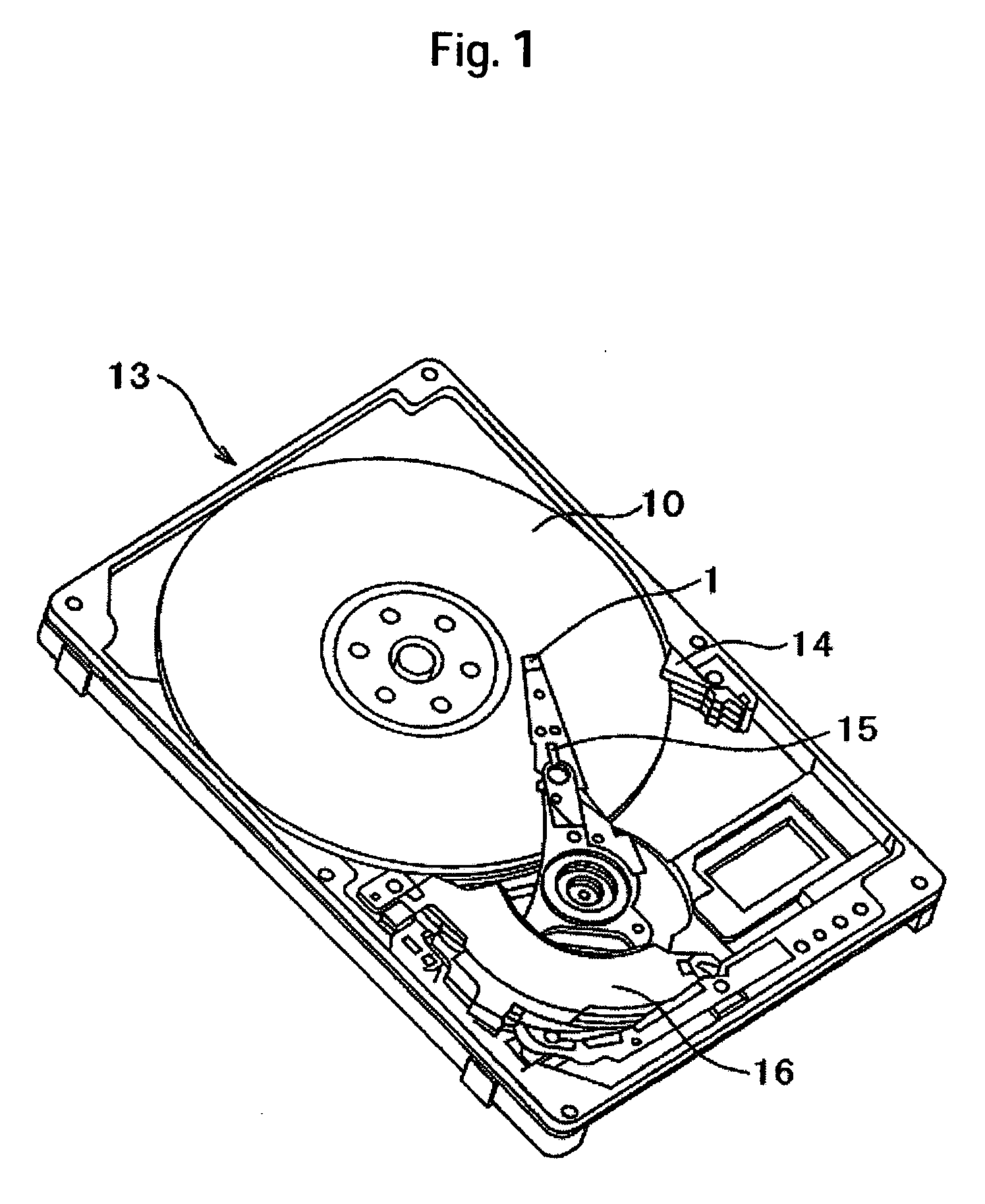
[0034] The whole constitution of the magnetic disk device according to the embodiment will be described with reference to FIG. 1 which is a perspective view of the magnetic disk device of this embodiment.

[0035] A magnetic disk device 13 is used as a hard disk device mounted on a computer or the like, and comprises a magnetic disk 10 disposed to freely rotate, a magnetic head slider (also simply called slider) 1 disposed so as to be opposed to the surface of the magnetic disk, and a drive unit for moving the magnetic head slider 1 in the radial direction of the surface of the magnetic disk 10. The magnetic disk device 13 generates an air stream between the magnetic disk 10 that rotates and the magnetic hea...


PUM


Abstract

Embodiments of the invention provide a magnetic disk device which lowers the cost, maintains reliability by compensating the thermal dent or protuberance caused by a change in the environmental temperature, makes it possible to increase the recording density by decreasing the floating amount of the slider, to increase the capacity of the device or to decrease the size thereof. In one embodiment, a magnetic disk device comprises a magnetic disk, a magnetic head slider, and a drive unit for moving the magnetic head slider, wherein an air stream is generated between the magnetic disk that rotates and the magnetic head slider to effect the recording or the reproduction in a state where the magnetic head slider is floating. The magnetic head slider includes a slider substrate portion and a thin-film head portion that has recording and reproducing elements, a metal film, and an insulating film formed on the slider substrate portion and constituting a slider-floating plane along with the slider substrate portion. The slider substrate portion includes a silicon substrate with a recessed portion, and a metal member buried in the recessed portion.

Description

CROSS-REFERENCES TO RELATED APPLICATIONS [0001] This application claims priority from Japanese Patent Application No. JP2005-072403, filed Mar. 15, 2005, the entire disclosure of which is incorporated herein by reference. BACKGROUND OF THE INVENTION [0002] This invention relates to a magnetic disk device, a magnetic head slider and a method of producing the same. More specifically, the invention relates to a magnetic head slider in which a thin-film head portion is formed on a silicon substrate portion, and a magnetic disk device using the magnetic head slider. The expression of recording / reproduction in the following description includes the recording only, reproduction only and both the recording and the reproduction. [0003] In a magnetic disk device, a magnetic head slider mounting a recording / reproducing element floats on the magnetic disk due to the pneumatic wedge film effect to record / reproduce the magnetic data recorded in the magnetic disk. To realize a high recording densi...

Claims


Application Information

Patent Timeline
IPC IPC(8): G11B5/60
CPCG11B5/6005G11B5/6082
Inventor KURITA, MASAYUKISHIRAMATSU, TOSHIYAETOH, KIMITOSHIYAMAZAKI, TAKANORI
Owner WESTERN DIGITAL TECH INC
Why Eureka
Try Eureka