
Image encoding apparatus, image decoding apparatus, control method therefor, computer program, and computer-readable storage medium

a technology of image encoding and decoding apparatus, applied in the direction of electrical apparatus, instruments, computing, etc., can solve the problem of low compression ratio, and achieve the effect of efficient encoding a natural image and relatively limited number of appearance colors

Inactive Publication Date: 2006-09-21
CANON KK
View PDF4 Cites 35 Cited by
  • Summary
  • Abstract
  • Description
  • Claims
  • Application Information

AI Technical Summary

Benefits of technology

[0018] The present invention has been made to overcome the conventional drawbacks, and has as its object to provide a technique of efficiently encoding a natural image (e.g., a photographic image), and a CG image and text image in which the number of appearance colors is relatively limited, and a decoding technique.

Problems solved by technology

In this case, a prediction error which is rarely or not generated sometimes exists though a short code length is assigned as a code length by entropy encoding, resulting in low compression ratio.

Method used


Image

  • Image encoding apparatus, image decoding apparatus, control method therefor, computer program, and computer-readable storage medium
  • Image encoding apparatus, image decoding apparatus, control method therefor, computer program, and computer-readable storage medium
  • Image encoding apparatus, image decoding apparatus, control method therefor, computer program, and computer-readable storage medium

Examples


first embodiment

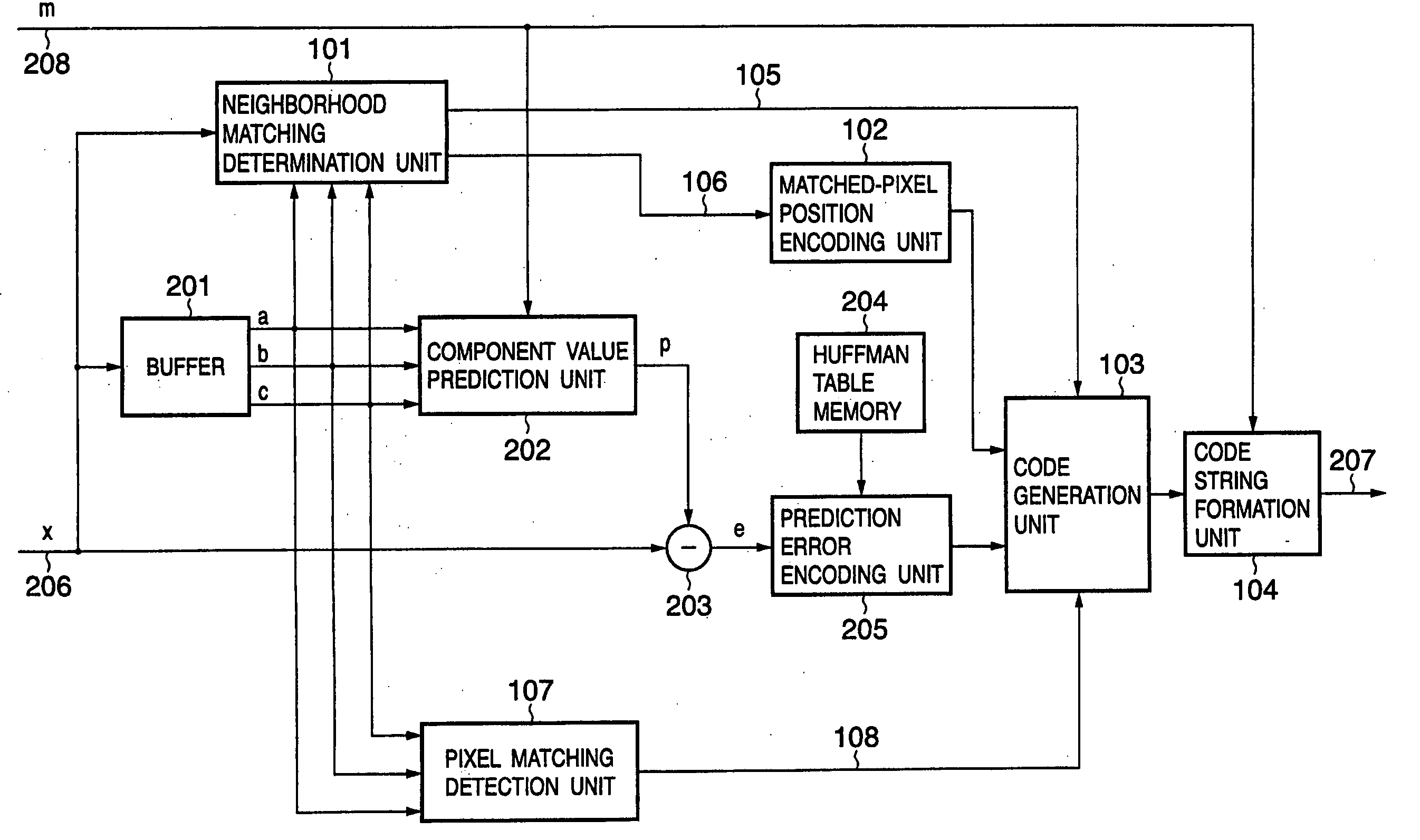
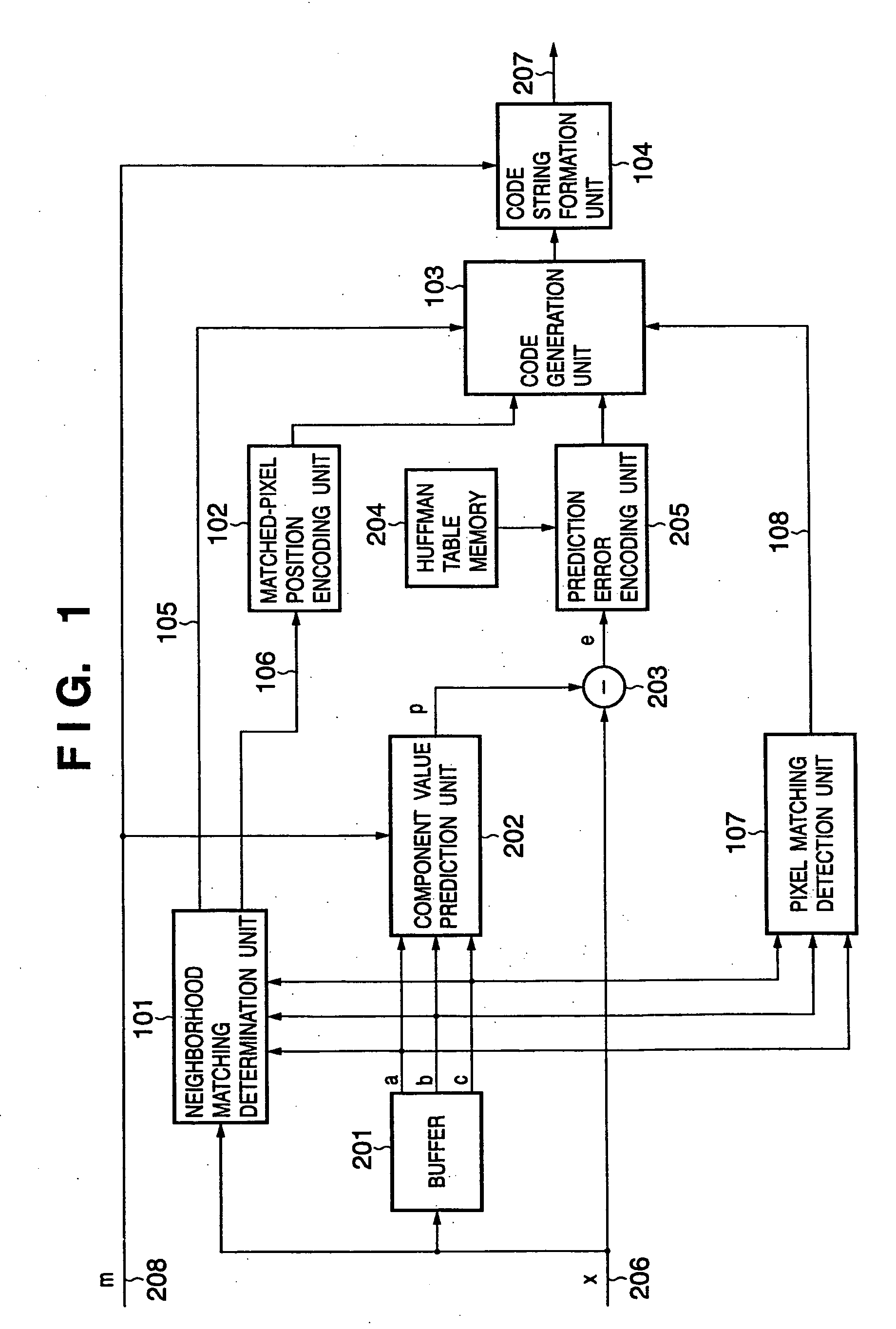
[0068]FIG. 1 is a block diagram showing an image processing apparatus according to the first embodiment.

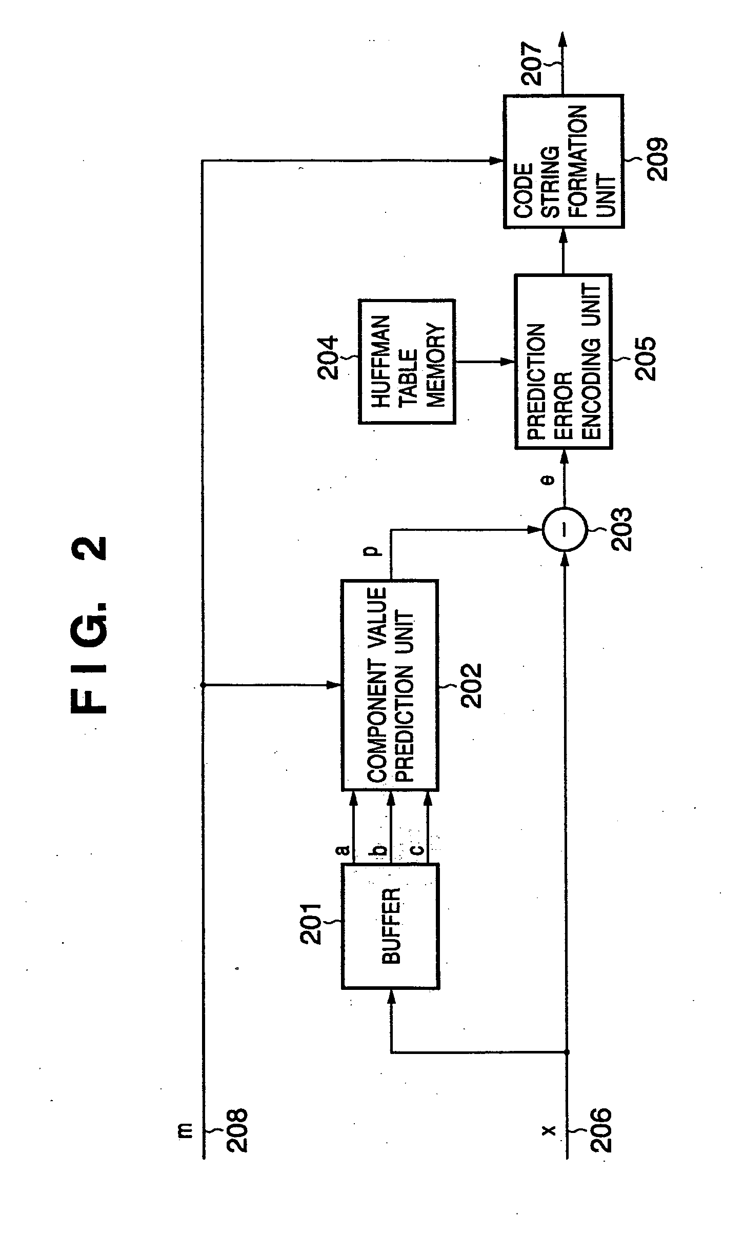
[0069] As shown in FIG. 1, the image processing apparatus according to the first embodiment comprises a neighborhood matching determination unit 101, matched-pixel position encoding unit 102, code generation unit 103, code string formation unit 104, buffer 201, component value prediction unit 202, and subtracter 203. The apparatus also comprises a Huffman table memory 204, prediction error encoding unit 205, and pixel matching detection unit 107. In FIG. 1, reference numerals 206, 207, 208, 105, 106, and 108 denote signal lines. The same reference numerals denote blocks which perform the same operations as those of processing blocks in the conventional image processing apparatus described in BACKGROUND OF THE INVENTION with reference to FIG. 2, and a description thereof will be omitted.

[0070] An image encoding process performed by the image processing apparatus according to the ...

modification to first embodiment

[0104] The first embodiment may be implemented by software. The modification will explain a case wherein the first embodiment is implemented by software.

[0105] When the first embodiment is implemented by software, processes corresponding to various building components typified by the neighborhood matching determination unit 101 shown in FIG. 1 are implemented by functions, subroutines, and the like in software. In the modification, the names of the processing units in FIG. 11 are directly used for descriptive convenience. A buffer 1201 and code buffer 1101 are allocated in a RAM 1402 by a CPU 1401 prior to the start of a process.

[0106]FIG. 14 is a block diagram showing the basic configuration of the apparatus when the apparatus is implemented by software.

[0107] In FIG. 14, the CPU 1401 controls the overall apparatus by using programs and data which are stored in the RAM 1402 and a ROM 1403. In addition, the CPU 1401 executes image encoding and decoding processes to be described l...

second embodiment

[0124] An example of decoding encoded data which is generated in the first embodiment (or its modification) will be described as the second embodiment. The decoding process is basically executed by procedures opposite to those of the encoding process in the image processing apparatus according to the first embodiment.

[0125]FIG. 11 is a block diagram showing an image processing apparatus which decodes encoded image data according to the second embodiment.

[0126] As shown in FIG. 11, the image processing apparatus according to the second embodiment comprises a code buffer 1101, header analysis unit 1102, matched-pixel position decoding unit 1103, prediction error decoding unit 1104, selector 1105, switch 1106, and buffer 1201. The apparatus also comprises a component value prediction unit 1202, adder 1111, and pixel matching detection unit 1150. In FIG. 11, reference numerals 1113, 1108, 1109, 1110, and 1112 denote signal lines.

[0127] A process performed by the image processing appa...


PUM


Abstract

According to this invention, while the encoding efficiency of image data (e.g., a natural image) substantially maintains the conventional one, an image (e.g., a CG image or text document) having a small number of appearance colors is losslessly encoded at higher compression ratio. For this purpose, pixel data are input in the raster order and temporarily stored in a buffer. Pixel data at positions having undergone encoding are stored. A neighborhood matching determination unit generates first information representing whether a pixel having the same color as that of the pixel of interest exists in neighboring pixels a, b, and c, and second information for specifying whether a pixel having the same color as that of the pixel of interest exists, and if the pixel having the same color exists, specifying the neighboring pixel. A pixel matching detection unit counts the number of colors contained in the neighboring pixels a, b, and c, and generates information representing whether the number of colors is two or less, or three or less. On the basis of the first information and second information, a code generation unit outputs one or both of encoded data from a matched-pixel position encoding unit and prediction error encoding unit.

Description

FIELD OF THE INVENTION [0001] The present invention relates to a technique of losslessly encoding / decoding an image. BACKGROUND OF THE INVENTION [0002] As a conventional method of configuring an image processing apparatus which losslessly encodes and decodes an image, a predictive coding-based method has been proposed. A predictive encoding apparatus generally has a string conversion unit which converts image data into a prediction error by predictive transform. The predictive encoding apparatus also has an entropy encoding unit which converts the prediction error output from the string conversion unit into encoded data of less redundancy by using entropy encoding such as Huffman encoding. [0003] JPEG (ITU-T T.81|ISO / IEC 10918-1) recommended as a still image coding scheme of an international standard by ISO and ITU-T defines a lossless coding scheme in which a lossless process is based on predictive coding. This lossless coding scheme will be called a JPEG lossless coding mode. In t...

Claims


Application Information

Patent Timeline
IPC IPC(8): G06K9/36G06K9/46
CPCH04N19/105H04N19/50H04N19/136H04N19/186H04N19/182
Inventor KAJIWARA, HIROSHIMATSUMOTO, YUKI
Owner CANON KK
Learn More