Disposable safety surgical blade

Inactive Publication Date: 2006-09-21
PL MEDICAL
View PDF11 Cites 63 Cited by
  • Summary
  • Abstract
  • Description
  • Claims
  • Application Information

AI Technical Summary

Benefits of technology

[0008] Those familiar with this field of endeavor will appreciate that one or more of advantages of the preferred embodiment include: (1) minimized waste by minimizing of the amount of material to be disposed; (2) lower tooling cost by locating of all the blade and carrier retention features on the same s

Problems solved by technology

The known devices may all perform their intended function, but none exhibits an ideal combi

Method used


Image

  • Disposable safety surgical blade
  • Disposable safety surgical blade
  • Disposable safety surgical blade

Examples


Embodiment Construction

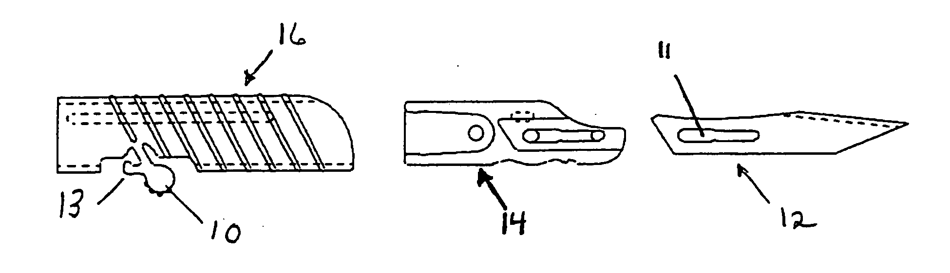
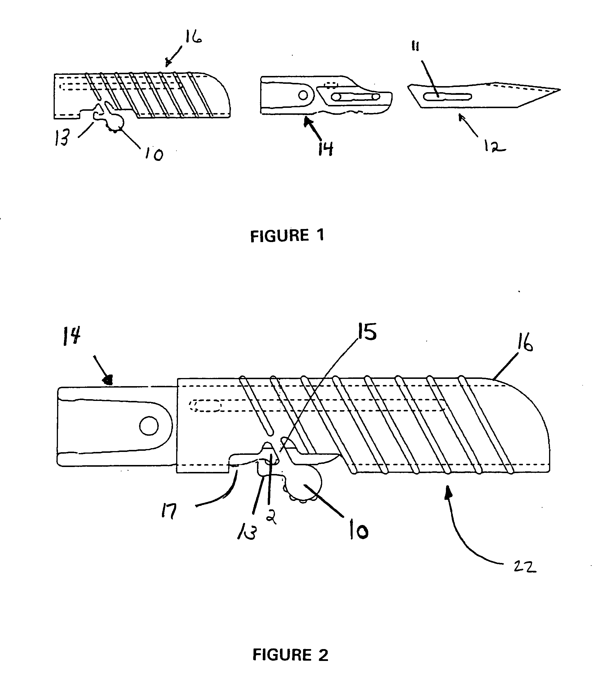
[0025] The present invention is directed to a safety scalpel assembly to be mounted on a customized reusable handle, preferably of stainless steel. As illustrated in FIG. 1, the pre-assembly or cartridge of the safety scalpel comprises three components: sleeve 16, blade carrier 14, and blade 12. FIG. 2 illustrates the sleeve 16, the blade carrier 14 and blade 12 (hidden from view) pre-assembled as a cartridge 22. The blade 12 may be any number of different shapes and sizes.

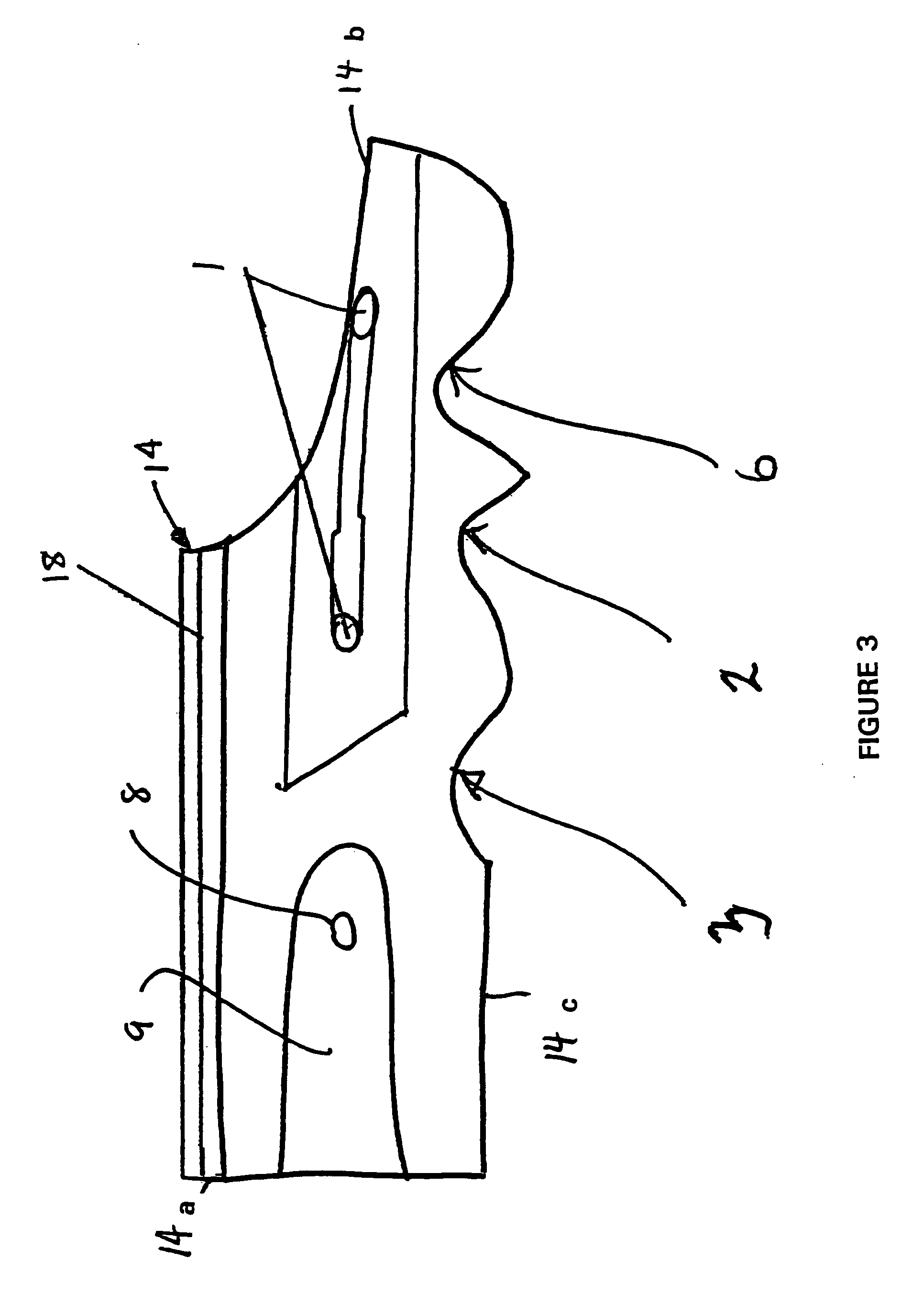
[0026] It is an aspect of the invention that blade carrier 14 and sleeve 16 are manufactured from durable materials able to withstand repeated sterilization by, typically, the fabricator. In one preferred embodiment the blade carrier 14 is injection molded using a suitable thermoplastic material. It is also preferred that sleeve 16 is transparent thermoplastic material to allow post-assembly visual inspection and identification of the blade 12. In another embodiment sleeve 16 can be non-transparent. As best seen ...


PUM


Abstract

A surgical scalpel assembly includes a blade carrier, a blade, a protective sleeve and a handle. The blade carrier has a number of notches and the protective sleeve has a depending tooth. The user positions the sleeve relative to the blade carrier and/or the handle by positioning the tooth to engage the notches. The blade carrier, blade, and protective sleeve are pre-assembled as a cartridge. A high volume yet safe method of assembly is also described.

Description

RELATED APPLICATION [0001] This application claims priority under 35 U.S.C. § 119(e) based on provisional application No. 60 / 663,375 filed Mar. 18, 2005.BACKGROUND OF THE INVENTION [0002] The present invention pertains to surgical scalpels, and in particular, such scalpels of the type that have a protective shield or the like whereby the blade can be selectively exposed or covered in use, then disposed of. [0003] Many scalpels of this type are known, such as described in the following U.S. patents and U.S. published applications: 3,793,7265,330,4945,527,3295,868,7715,919,2015,938,6765,938,675  941,8926,053,9296,626,9252004 / 0243161D490,153[0004] The general concept of a blade carrier attachable to a handle and to the blade itself, with an integral or separate protective sleeve or guide for the blade that is moveable to at least two positions, is well known. Moreover, the further refinement of the blade carrier with associated blade being detachable from the handle for disposal, whil...

Claims


Application Information

Patent Timeline
IPC IPC(8): A61B17/32
CPCA61B17/3213A61B17/3215A61B2017/00526A61B2017/00907A61B2017/32113
Inventor DJORDJEVIC, ILIJAKANWAR, SUSHIL K.
Owner PL MEDICAL
Why Eureka
Try Eureka