Pressure sensor device and pressure sensor cell thereof
- Summary
- Abstract
- Description
- Claims
- Application Information
AI Technical Summary
Benefits of technology
Problems solved by technology
Method used
Image

Examples
first embodiment
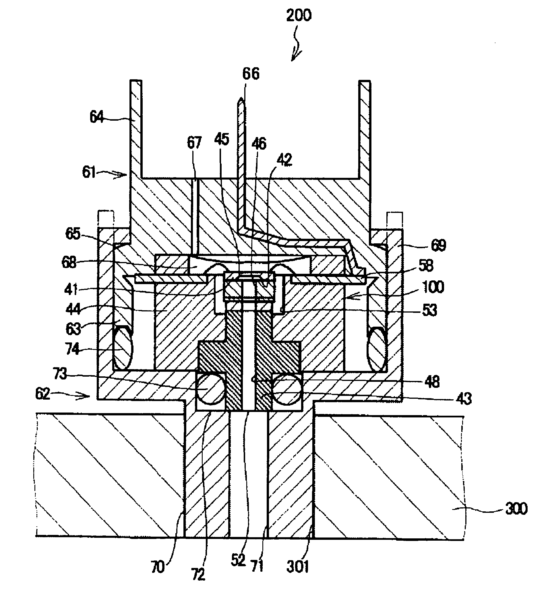
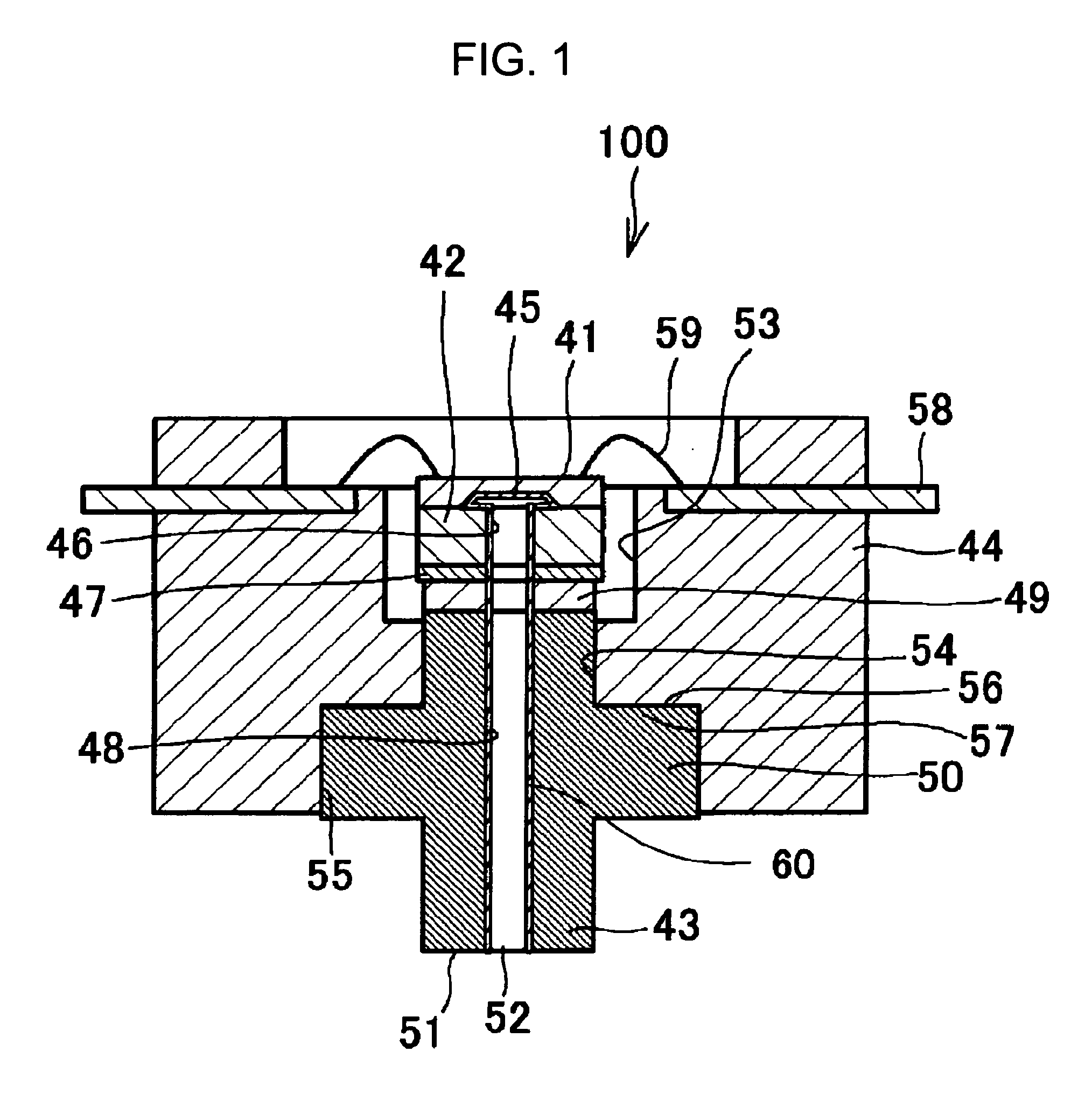
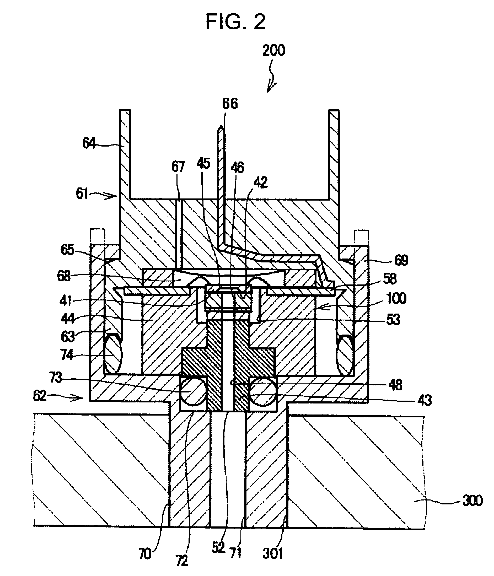
[0067]FIG. 2 is a cross sectional view showing a pressure sensor device 200 according to the present invention. The pressure sensor device 200 incorporates the pressure sensor cell 100 of FIG. 1, and is mountable to an enclosure 300 with a mounting means. The mounting means can include a connector member 61 and a joint member 62. The end of the joint member 62 is then bent or crimped over around the side of the connector member 61 to engage the connector member 61 and integrate the pressure sensor cell 100, the connector member 61, and the joint member 62. Note that the protective film 60, which is not illustrated here, can be included to protect the joining member 49.
[0068] The connector member 61 can include a housing section 63 for containing the pressure sensor cell 100 and a socket section 64 for connecting the output of the pressure sensor device 200 to the outside. The housing section 63 and the socket section 64 can be integrally molded together. The socket section 64 has an...
second embodiment
[0076]FIG. 3 is a cross sectional view showing a pressure sensor device according to the present invention. The pressure sensor device includes the pressure sensor cell 100 mounted to the enclosure 300 with a mounting means, which includes a fixture 310 and fasteners 311, such as screws. Namely, in the enclosure 300, a first stepped recess 302 is provided for containing the pressure sensor cell 100. Moreover, the fixture 310 is set over the enclosure 300 and the pressure sensor cell 100 and secured to the enclosure 300 with the screws 311. The pressure sensor cell 100 is secured to the fixture 310 by the pressure applied to the pressure sensor cell 100 from the pressure introducing port 52 and reaction force applied from the fixture 310 against the pressure. Again, the protective film 60, which is not illustrated here, can be included to protect the joining member 49.
[0077] A second recess 303 is formed at the bottom of the recess 302. The second stepped recess 303 accommodates the ...
fourth embodiment
[0091]FIG. 6 is a cross sectional view showing a pressure sensor device according to the present invention. Here, the pressure sensor device 201, is similar to the embodiment of FIG. 2, but includes the pressure sensor cell 101 of FIG. 5 held between the connector member 61 and the joint member 62. An end of the joint member 62 is then bent or crimped over around the connector member 61 to engage the same to thereby integrate the pressure sensor cell 101, the connector member 61, and the joint member 62. The arrangement of the connector member 61 and the joint member 62 is otherwise the same as that of the embodiment of FIG. 2. Again, the protective film 60, which is not illustrated here, can be included to protect the joining member 49.
[0092] The end face of the pressure sensor cell 101 on the opposite side of the open end 151, where the pressure introducing port 152 is opened, can be bonded to the end face (a disposing section) of a partition between the housing section 63 and the...
PUM
 Abstract
Description
Claims
Application Information
 - Generate Ideas
- Intellectual Property
- Life Sciences
- Materials
- Tech Scout
- Unparalleled Data Quality
- Higher Quality Content
- 60% Fewer Hallucinations
Browse by: Latest US Patents, China's latest patents, Technical Efficacy Thesaurus, Application Domain, Technology Topic, Popular Technical Reports.
© 2025 PatSnap. All rights reserved.Legal|Privacy policy|Modern Slavery Act Transparency Statement|Sitemap|About US| Contact US: help@patsnap.com