Apparatus for storing lengths of pipe

Inactive Publication Date: 2006-09-28
TRISLER JAMES
View PDF30 Cites 8 Cited by
  • Summary
  • Abstract
  • Description
  • Claims
  • Application Information

AI Technical Summary

Benefits of technology

[0003] The present invention provides a novel system that allows such pipes to be stored, even in several layers, and allows individual pipes to be removed, as needed, safely and easily.
[0004] According to the invention, pipe racks and strips for supporting additional layers of pipe are provided with novel and safe pipe stop devices that can easily be moved from a stop position to a retracted, or withdrawn, position, allowing removal of individual pipes. According to certain embodiments of the invention, movement from the stop position to the retracted position occurs in the direction away from a pipe in contact with the device, thereby facilitating operation of the device. According to other embodiments of the invention, the pipe stop is removed in order to permit removal of a length of pipe.

Problems solved by technology

Among these are that they do not create safe conditions for operating personnel, are difficult to use, particularly when several layers of pipe are to be stored, and allow removal of individual lengths of pipe only with difficulty.

Method used


Image

  • Apparatus for storing lengths of pipe
  • Apparatus for storing lengths of pipe
  • Apparatus for storing lengths of pipe

Examples


Embodiment Construction

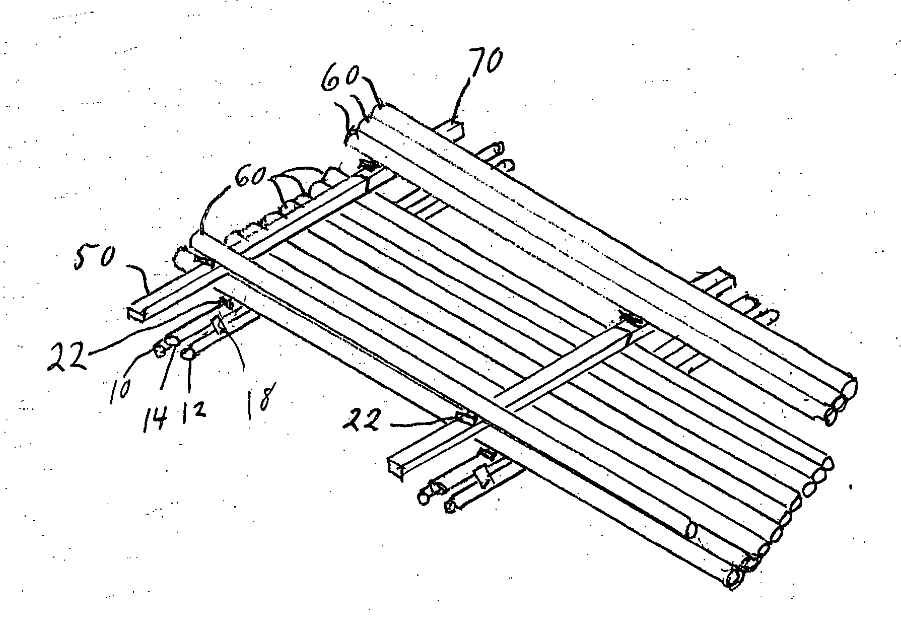
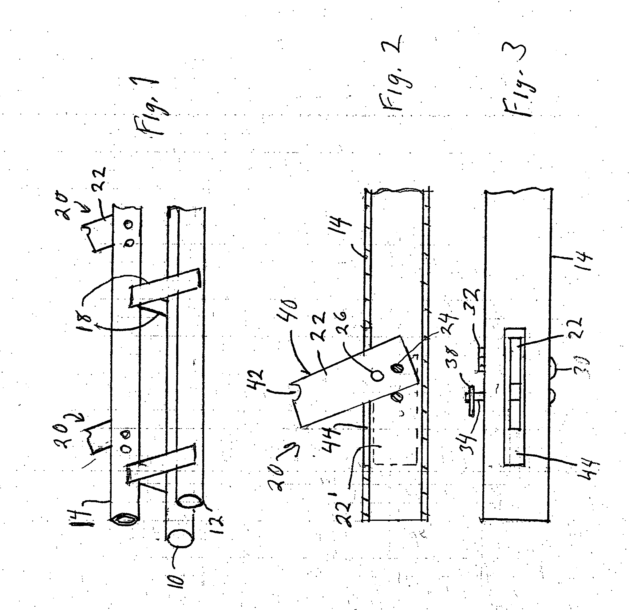
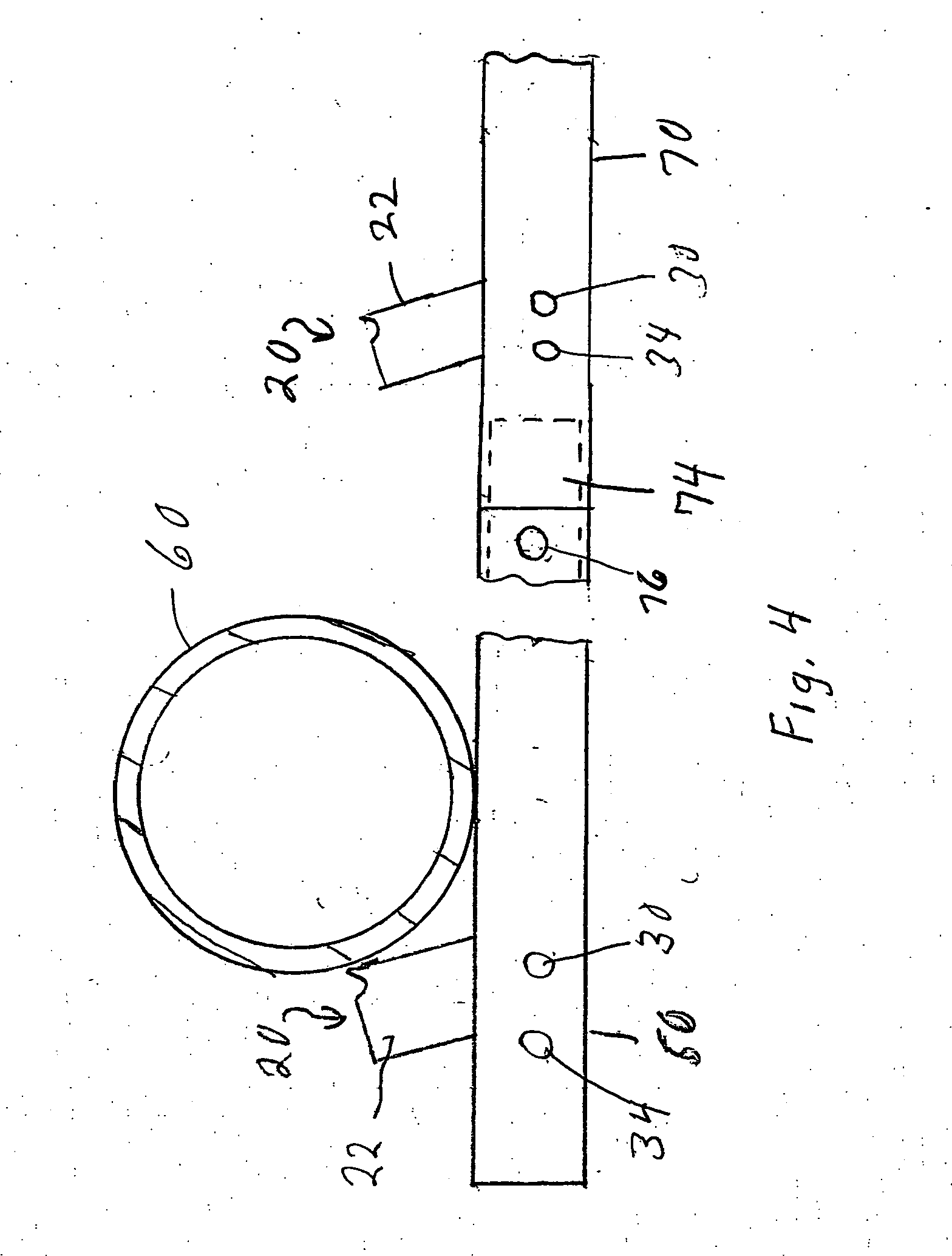
[0013]FIGS. 1, 2 and 3 show one end of a pipe rack provided with pipe stop elements according to one embodiment of the invention. The rack is composed of first and second tubular base elements 10 and 12 and an elongated pipe supporting element 14. At least element 14 is hollow, while base elements 10 and 12 may or may not be hollow. Element 14 is secured to elements 10 and 12 by supporting plates, or tubes, etc., 18, each welded to element 14 and to a respective one of elements 10 and 12 to provide a rigid structure. Connecting elements may also be welded between base elements 10 and 12 for added rigidity. Other forms of connection among elements 10, 12 and 14 can obviously be employed. For example, these could include triangular plates each vertex of which is connected to a respective tubular element.

[0014] While elements 10, 12 and 14 have been illustrated to have a circular cross-section, it will be appreciated that they can have other cross-sections, such as square or rectangul...


PUM


Abstract

A device for supporting a group of pipes during temporary storage, the device being composed of: an elongated pipe supporting element having a pipe supporting surface; and at least one safety stop assembly including a pipe stop member and at least one fastening element, wherein the pipe stop member is movable relative to the pipe supporting element between a stop position and a retracted, or withdrawn position, the stop member being operative, when in the stop position, to prevent removal of pipes from the pipe supporting element, and the stop member being operative, when in the retracted, or withdrawn, position, to allow removal of pipes from the pipe supporting element, and the at least one fastening element being connectable between the pipe supporting element and the pipe stop member for holding the pipe stop member in the stop position.

Description

BACKGROUND OF THE INVENTION [0001] The present invention relates to systems for storing lengths of pipe in industries such as oil and gas drilling. [0002] Oil and gas drilling operations require the availability of a number of lengths of pipe that are added sequentially to pipe strings in order to drill a well. Heretofore, many arrangements have been used for temporary storage of the pipes prior to use. The known arrangements present a number of drawbacks. Among these are that they do not create safe conditions for operating personnel, are difficult to use, particularly when several layers of pipe are to be stored, and allow removal of individual lengths of pipe only with difficulty. BRIEF SUMMARY OF THE INVENTION [0003] The present invention provides a novel system that allows such pipes to be stored, even in several layers, and allows individual pipes to be removed, as needed, safely and easily. [0004] According to the invention, pipe racks and strips for supporting additional lay...

Claims


Application Information

Patent Timeline
IPC IPC(8): E21B19/14
CPCE21B19/15
Inventor TRISLER, JAMES
Owner TRISLER JAMES
Why Eureka
Try Eureka