Shock-absorbing bearing for timepiece

a timepiece and bearing technology, applied in mechanical clocks, instruments, horology, etc., can solve the problems of design problems, increased handling complexity, and the risk of losing the spring which measures less than 2 mm

Active Publication Date: 2006-09-28
ROLEX SA
View PDF4 Cites 20 Cited by
  • Summary
  • Abstract
  • Description
  • Claims
  • Application Information

AI Technical Summary

Benefits of technology

[0026] Shock tests conducted on shock-absorbing bearings as proposed by the present invention have shown that the shock-absorbing spring withstands even the most severe shocks without becoming disengaged from the bearing support. In extreme cases, abnormal shocks can cause a plastic deformation of the shock-absorbing spring. However, this has no troublesome effects on the movement of the watch, which can continue to operate normally since the shock-absorbing bearing retains its integrity, even if its shock-absorbing properties have been decreased.

Problems solved by technology

These dimensions give rise to design problems as regards both the elastic limits and plastic deformation, particularly during the fixing of the spring, the retention of the spring in case of shock, the mounting of the spring, and the mounting and dismantling of the bearing.
With most shock-absorbing springs, it is found that either the shock-absorbing spring must be positioned before the bearing support is pressed into the bridge or plate, making it necessary to extract the bearing support in order to dismantle the bearing, or, if the extraction of the support is not necessary, the hinge of the shock-absorbing spring fails to remain in place when the spring is disengaged from the support, creating a risk of losing the spring which measures less than 2 mm.
The watchmaker must therefore identify the side of the spring acting as a hinge and the site of the bearing support shaped to receive this hinge, which, because of the dimensions, makes handling even more complicated, with the constant risk of losing the spring.
The principal drawback of this bearing arises from the fact that the central support element of the shock-absorbing spring is connected to the bearing support by four arms, each of which has a length which is reduced by half compared with the total dimension of each of the two suspension elements linking the central support element to the bearing support.
In view of the very small dimensions of such a shock-absorbing spring, the halving of the length of the arms linking this central support element to the bearing support gives rise to a problem with respect to the consequent reduction of the elastic limit, so that this limit can easily be exceeded during the fastening of the arms for linking the shock-absorbing spring to the bearing support.

Method used


Image

  • Shock-absorbing bearing for timepiece
  • Shock-absorbing bearing for timepiece
  • Shock-absorbing bearing for timepiece

Examples


Embodiment Construction

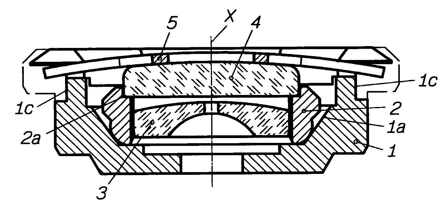
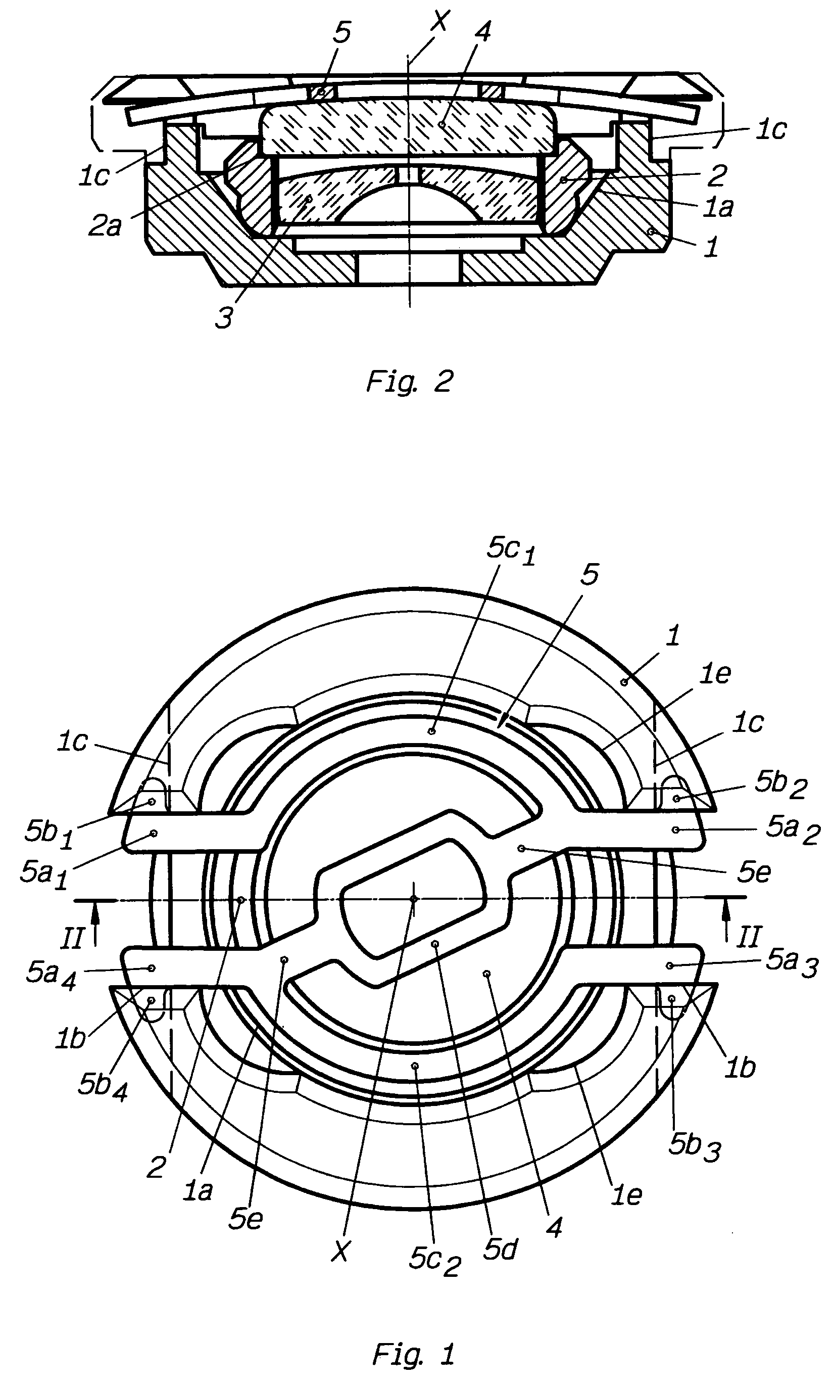
[0031] The bearing shown in FIGS. 1 and 2 has a bearing block 1 comprising a seat in the form of a truncated conical cup 1a for positioning a chaton 2 which has a cylindrical part into which a pierced jewel 3 is pressed and which has a seat 2a for an endstone 4. A shock-absorbing spring 5 is fixed to the bearing block 1 to retain the chaton 2 and the endstone 4 in an elastic way in their respective seats 1a, 2a.

[0032] The bearing block 1 has the characteristic of being entirely symmetrical with respect to all the planes containing the pivot axis X of the bearing. A diametric milled area 1b is formed on the upper part of this bearing block and two parallel milled areas 1c, perpendicular to the diametric milled area 1b, are formed on the outside of the bearing block 1, in its thickness, at a certain distance from its upper face.

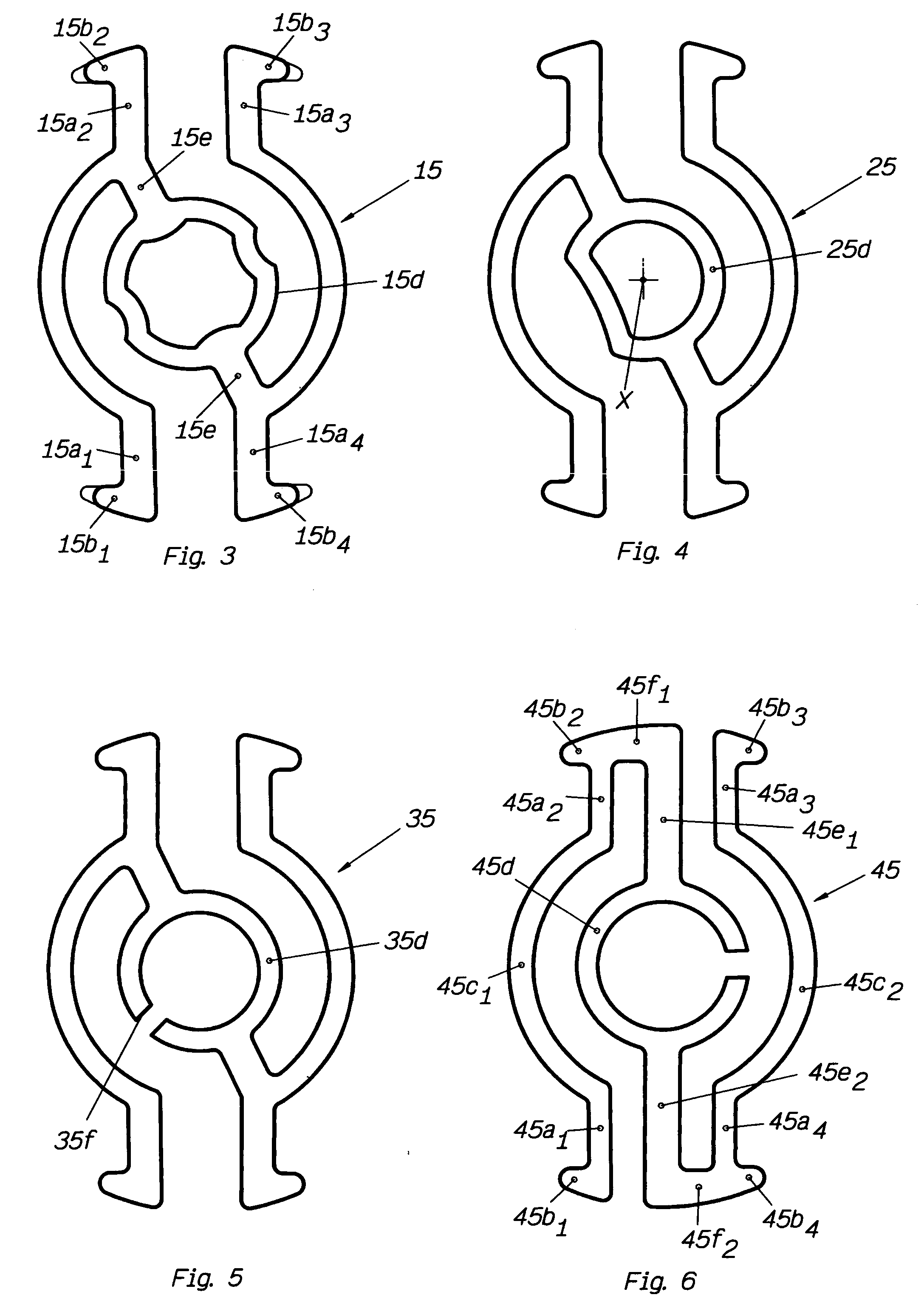
[0033] These three milled areas 1b, 1c are designed for the fixing of the four linking arms 5a1, 5a2, 5a3, 5a4 of the shock-absorbing spring 5, the two arms ...


PUM


Abstract

This shock-absorbing bearing comprises a bearing block (1), a pierced jewel (3), an endstone (4) and a shock-absorbing spring (5) connected to said bearing block (1) by four linking arms (5a1, 5a2, 5a3, 5a4), parallel to a plane containing the pivot axis (X) of said bearing and forming two suspension elements (5a1, 5c1, 5a2; 5a3, 5c2, 5a4), each having two of said linking arms connected to each other by a branch in the form of an arc (5c1, 5c2) centered on said pivot axis (X) and having a radius greater than that of said endstone (4), these suspension elements being connected to each other by two diametric arms (5e) located on either side of a central support element (5d). The outer ends of said diametric arms (5e) are connected to two of said linking arms (5a2, 5a4) belonging to said respective suspension elements (5a1, 5c1, 5a2; 5a3, 5c2, 5a4).

Description

CROSS REFERENCE TO RELATED APPLICATIONS [0001] This application claims priority of European Application No. 05405263.4 filed Mar. 23, 2005, which is included in its entirety by reference made hereto. BACKGROUND OF THE INVENTION [0002] 1. Field of the Invention [0003] The present invention relates to a shock-absorbing bearing for a timepiece, comprising a bearing block, a pierced bearing jewel, a seat for positioning this bearing jewel in this bearing block, an endstone, a seat for positioning this endstone in this bearing block, and a shock-absorbing spring to hold said endstone against said positioning seat, this shock-absorbing spring being connected to said bearing block by four linking arms, parallel to a plane containing the pivot axis of said bearing, and forming, on each side of this plane, a suspension element having two of said linking arms connected to each other by a branch in the form of an arc centered on said pivot axis and having a radius different from that of said e...

Claims


Application Information

Patent Timeline
Patent Type & Authority Applications(United States)
IPC IPC(8): G04B29/00
CPCG04B31/04
Inventor KOHLER, MICHELVOIROL, ROMAIN
Owner ROLEX SA
Why Eureka
Try Eureka