
Video camera and image extracting apparatus utilized for same

Active Publication Date: 2006-09-28
XACTI CORP
View PDF3 Cites 26 Cited by
  • Summary
  • Abstract
  • Description
  • Claims
  • Application Information

AI Technical Summary

Benefits of technology

[0007] Another object of the present invention is to provide an image extracting apparatus capable of executing a good camera shake correction under a high zoom magnification.
[0033] Similarly to the invention according to claim 9, it is possible to realize a good camera-shake correction operation.

Problems solved by technology

It should be noted that the longer a focal length of an imaging optical system is (the higher the zoom magnification is), the more the degree of limitation of the camera-shake correction performance is.
Whereas, in the prior art, as the zoom magnification is higher, the camera-shake correction performance is substantially limited, and therefore, it is impossible to properly prevent a camera shake in photographing under a high magnification.

Method used


Image

  • Video camera and image extracting apparatus utilized for same
  • Video camera and image extracting apparatus utilized for same
  • Video camera and image extracting apparatus utilized for same

Examples


Embodiment Construction

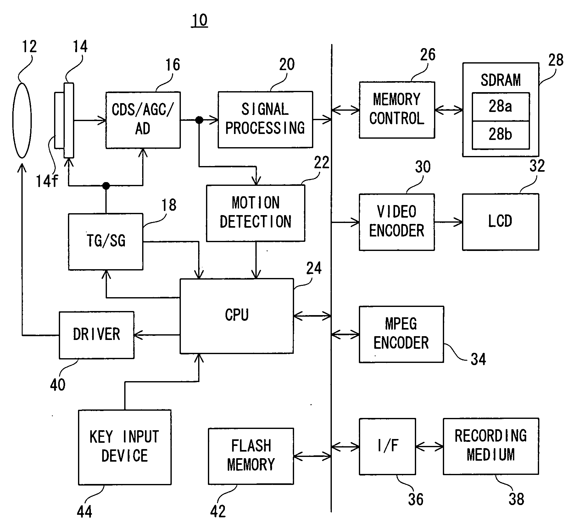
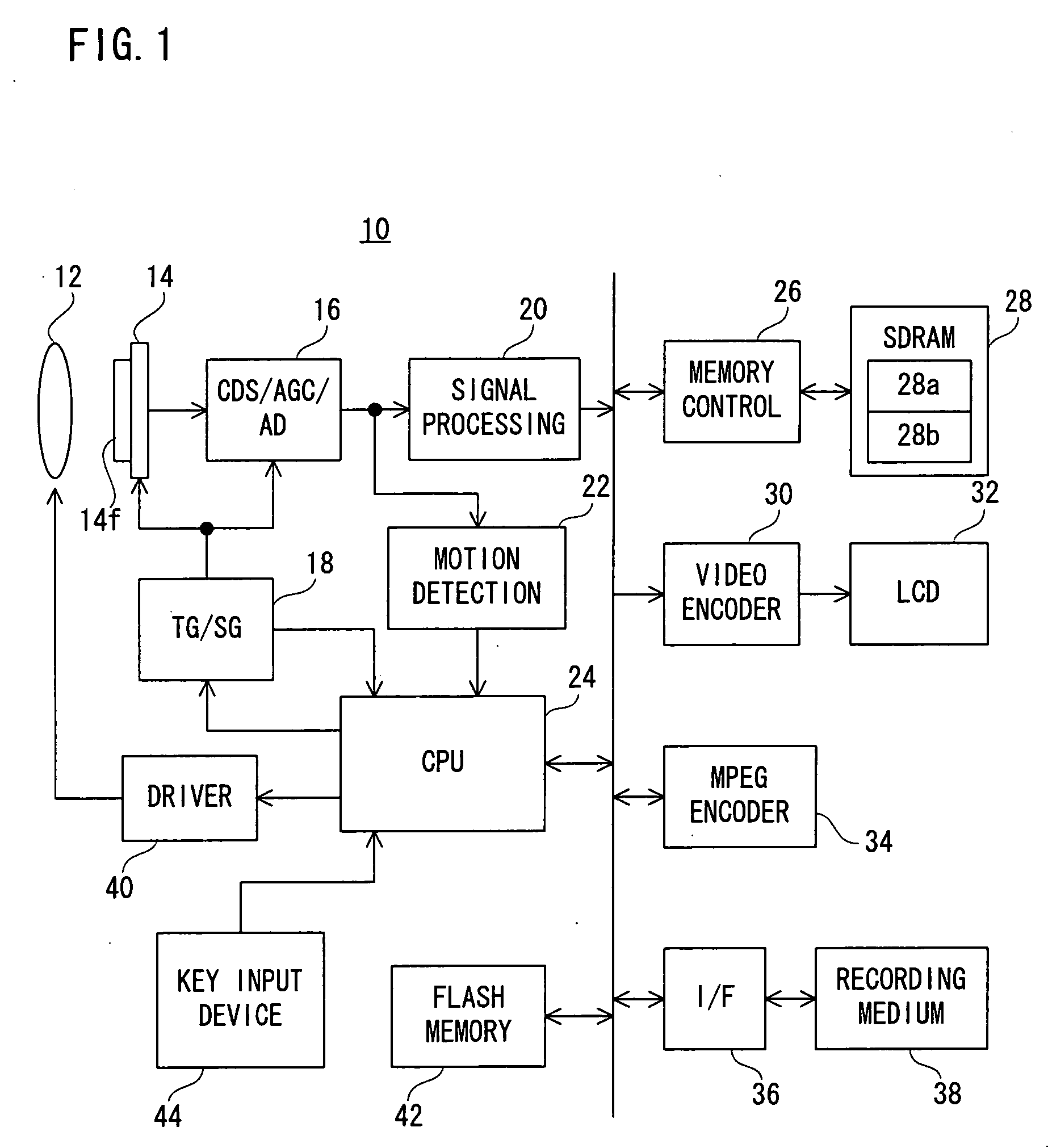
[0045] Referring to FIG. 1, a digital video camera 10 of this embodiment includes a zoom lens 12. An optical image of an object scene is irradiated onto an imaging surface 14f of an image sensor 14 through the zoom lens 12, and is subjected to a photoelectronic conversion. Thus, electric charges representing an object scene image, that is, raw image signals are generated.

[0046] When a power source is turned on, a CPU 24 instructs a TG / SG 18 to repeatedly perform an exposure and a charge reading. The TG / SG 18 applies a plurality of timing signals to the image sensor 14 to execute an exposure of the imaging surface 14f of the image sensor 14 and a reading of the electric charge thus obtained. The raw image signal generated by the imaging surface 14f is read in the order according to raster scanning in response to a vertical synchronization signal Vsync output per 1 / 30 seconds.

[0047] The raw image signal output from the image sensor 14 is subjected to a series of processes such as a ...


PUM


Abstract

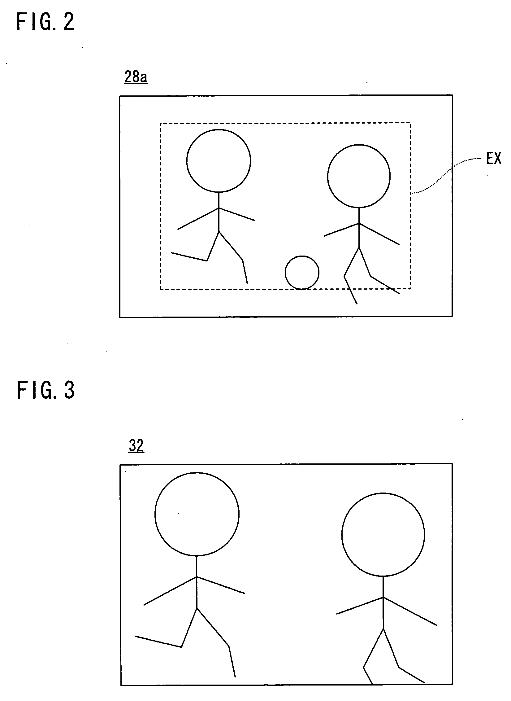
A video camera includes an LCD monitor. On the LCD monitor, an object scene image belonging to a camera-shake correction area out of the object scene image captured by an imaging surface is displayed. A CPU determines whether or not a movement of the object scene image captured by the imaging surface satisfies a pan / tilt condition or a camera-shake condition referring to a threshold value. The threshold value is set to a large numerical value as a zoom magnification is high. A camera-shake condition determining process is started in place of a pan / tilt condition determining process when the pan / tilt condition is satisfied. Also, the pan / tilt condition determining process is started in place of the camera-shake condition determining process when the camera-shake condition is satisfied. In addition, the camera-shake correction area is moved in such a direction as to cancel the movement of the object scene image captured by the imaging surface when the pan / tilt condition is not satisfied.

Description

CROSS REFERENCE OF RELATED APPLICATION [0001] The disclosure of Japanese Patent Application No. 2006-44696 is incorporated herein by reference. BACKGROUND OF THE INVENTION [0002] 1. Field of the Invention [0003] The present invention relates to an image extracting apparatus and a video camera. More specifically, the present invention relates to an image extracting apparatus which extracts a partial object scene image belonging to a specific area out of an object scene image captured by an imaging surface. [0004] 2. Description of the Prior Art [0005] An example of such a kind of conventional apparatus is disclosed in a Patent Document 1 (Japanese Patent Laying-open No. 11-183951). The prior art is for restricting a camera-shake correction performance in panning / tilting in order to prevent an erroneous camera-shake correction operation in response to the panning / tilting. It should be noted that the longer a focal length of an imaging optical system is (the higher the zoom magnificati...

Claims


Application Information

Patent Timeline
IPC IPC(8): G03B17/00
CPCG03B5/02G03B17/02G03B17/20G03B2205/0007H04N5/23248H04N5/23254H04N5/23258H04N5/23261H04N5/23293H04N5/23296G03B2217/005H04N23/68H04N23/6811H04N23/6815H04N23/6812H04N23/63H04N23/69
Inventor YAMANOUCHI, AKIKOTOBA, AKIRA
Owner XACTI CORP
Learn More