

Image forming device
a technology of image forming device and forming sheet, which is applied in the direction of electrographic process apparatus, instruments, optics, etc., can solve the problems of image loss, increased amount of developer recovered by cleaning means after not being transferred to the sheet, and loss of image transferred to the sheet. , to achieve the effect of preventing image loss
- Summary
- Abstract
- Description
- Claims
- Application Information
AI Technical Summary
Benefits of technology
Problems solved by technology
Method used
Image

Examples
first embodiment
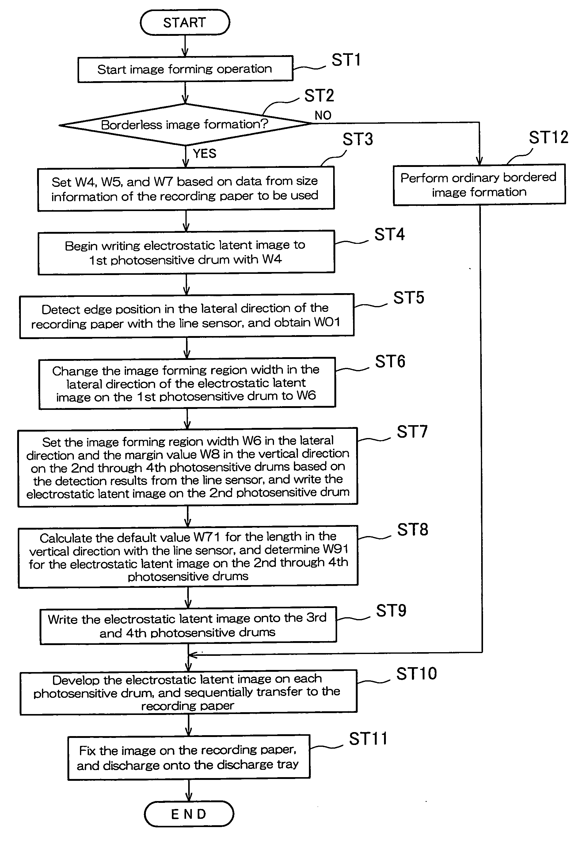
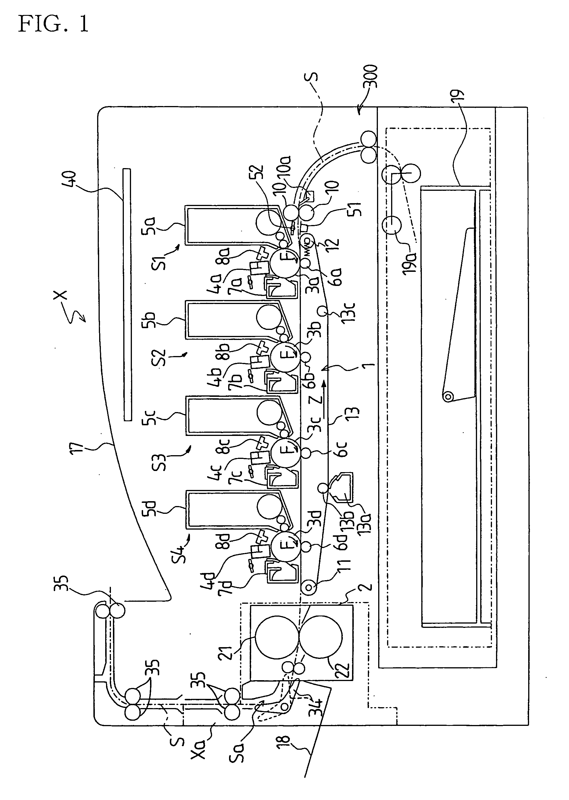
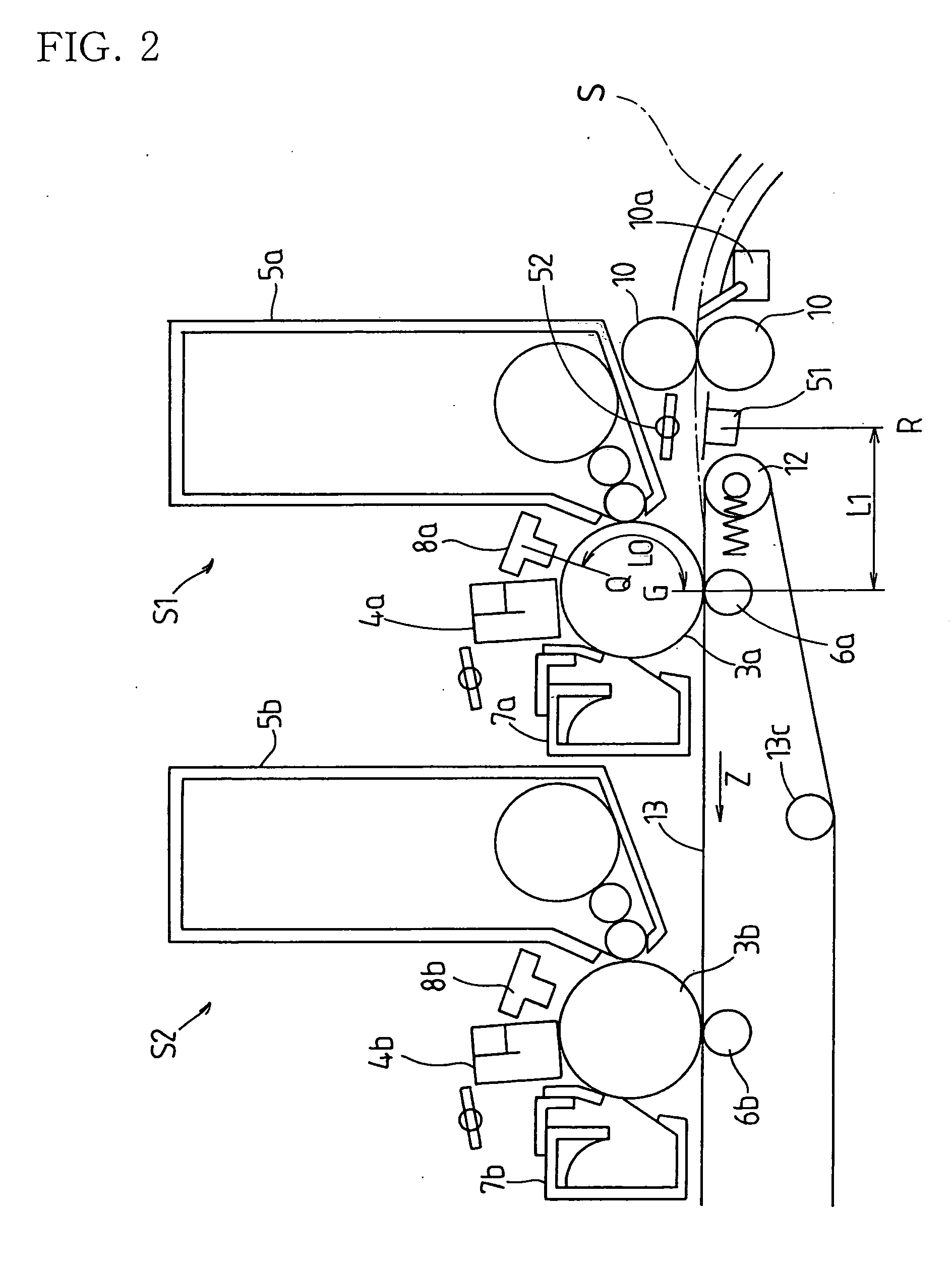
[0074]FIG. 1 shows the relevant portions of an electrophotographic image forming apparatus associated with a first embodiment of the present invention. A transfer / transport belt mechanism 1 is provided in this image forming apparatus X. This transfer / transport belt mechanism 1 includes a drive roller 11 on one side (the left side of FIG. 1) supported such that it can rotate, an idler roller 12 in the other side (the right side of FIG. 1) supported such that it can rotate, and an endless transfer / transport belt 13 as a sheet carrier that is driven in the direction of arrow Z shown in FIG. 1, extended between the rollers 11 and 12. By electrostatically attracting a recording paper P as the sheet on the surface of this transfer / transport belt 13, the recording paper P, supplied from registration rollers 10 as a registration means, is transported from the other side (the upstream side) to the one side (the downstream side). The registration rollers 10 temporarily hold the recording pape...
second embodiment
[0122] In the first embodiment described above, the line sensor 51 detects only the edge position of the recording paper P. This can be changed such that the edge position of the recording paper P is detected at two locations in the recording paper transport direction, making it possible to detect a skew state of the recording paper P, as described below as a second embodiment. Parts that are the same as in the first embodiment are given the same reference numerals, and primarily the differing points of this second embodiment are explained.
[0123]FIG. 11 is a schematic view that shows the configuration of the vicinity of the first and second photosensitive drums in the second embodiment. FIG. 12 is a plan view that illustrates a skew state of the recording paper, viewed from above the transfer / transport belt.
[0124] The line sensor 51 detects the edge position of the recording paper P transported towards the transfer point G at two locations in the paper transport direction (includi...
third embodiment
[0155] In the third embodiment of the present invention, the settings for the distance from the detection point of the line sensor to the transfer point and the distance from the writing point of the exposing means to the transfer point are changed. This is explained with reference to FIG. 20 and FIG. 21. Except for the settings for the distance from the detection point of the line sensor to the transfer point and the distance from the writing point of the exposing means to the transfer point, the configuration is the same as in the case of the second embodiment. Parts that are the same are given the same numerals, and a detailed explanation of those parts is omitted.
[0156] In this third embodiment, the distance from the detection point of the edge position of the recording paper P detected by the line sensor to the transfer point is set such that it is quite longer than the distance from the writing point of the electrostatic latent image (image) written to the first photosensitiv...
PUM
 Abstract
Description
Claims
Application Information