Battery module
a battery module and battery technology, applied in the field of batteries, can solve the problems of battery module explosion, deterioration of charge/discharge efficiency, battery module performance degradation, etc., and achieve the effect of maximizing cooling efficiency
- Summary
- Abstract
- Description
- Claims
- Application Information
AI Technical Summary
Benefits of technology
Problems solved by technology
Method used
Image
Examples
third embodiment
[0071] A battery module of this embodiment is identical to that of FIG. 5 except that the thermoelectric elements of the third embodiment are replaced with heat dissipation ribs 44.
[0072] The heat dissipation ribs 44 are arranged on an inner surface of the cooling tube 12 and spaced apart from each other by a predetermined distance. The heat dissipation ribs 44 may extend in a direction where the cooling air flows.
[0073] The heat dissipation ribs 44 may be formed of a material identical to that of the cooling tube 42. In this case, the heat dissipation ribs 44 may be simultaneously formed with the cooling tube 42. That is, the heat dissipation ribs 44 can be integrally formed with the cooling tube 42. Alternatively, the heat dissipation ribs 44 may be formed of a material having a thermal conductivity higher than that of the cooling tube 12.
sixth embodiment
[0074]FIG. 8 shows a battery module according to the present invention.
[0075] A battery module of this embodiment is identical to that of FIG. 7 except that arranged locations of the heat dissipation ribs are exchanged with arranged locations of the unit batteries.
[0076] That is, in this embodiment, insertion cases 56 in which unit batteries 54 are respectively inserted are mounted on an inner surface of the cooling tube 52 and heat dissipation ribs 58 are arranged on an outer surface of the cooling tube 52.
[0077] The operation of the battery module of the present invention will now be described with reference to FIGS. 1 and 2.
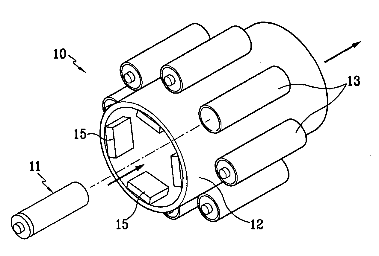
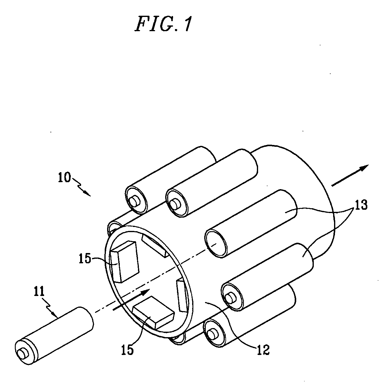
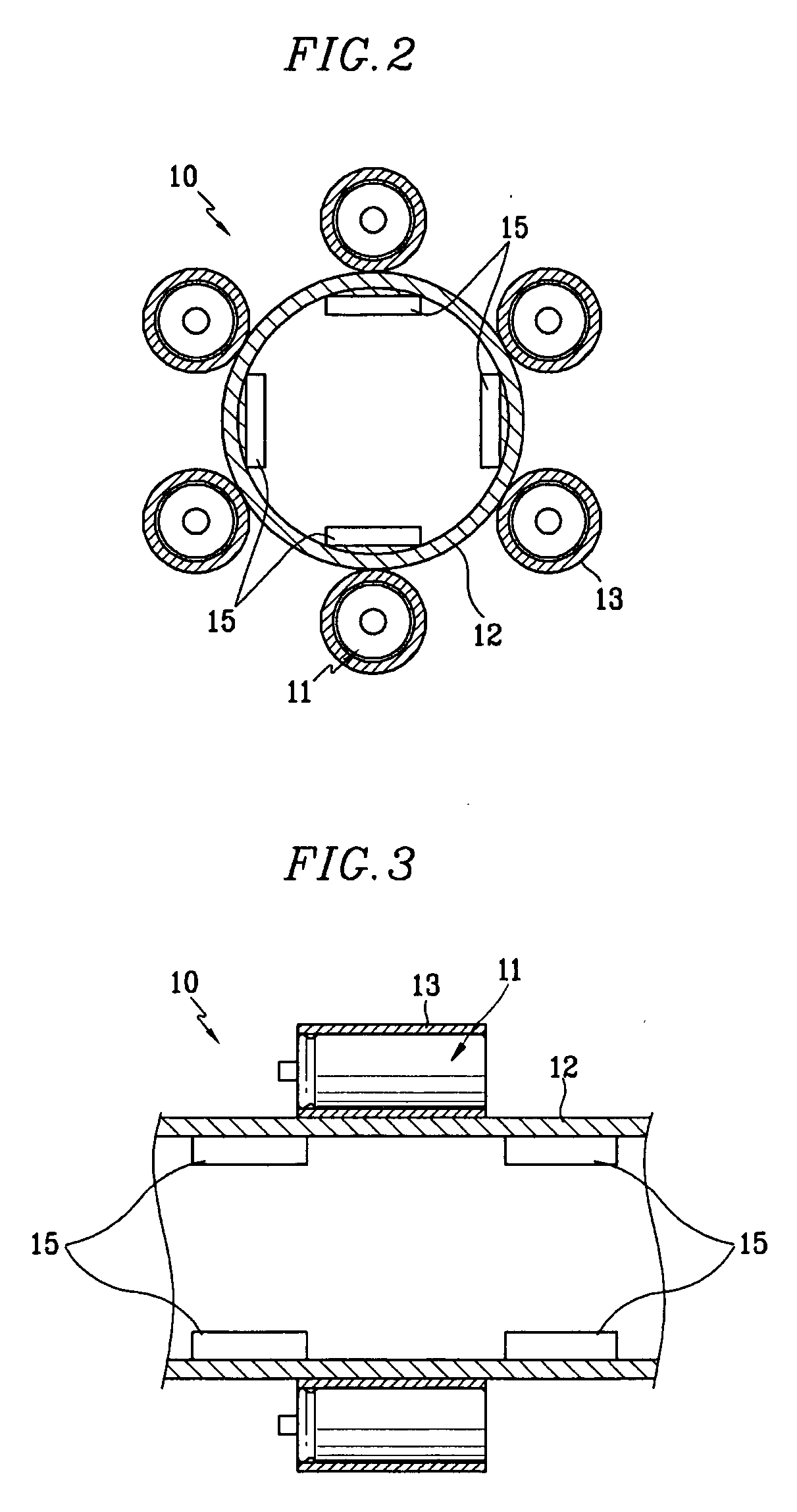
[0078] As described above, the unit batteries 11 are arranged on the cooling tube 12 functioning as a housing. Heat generated from the unit batteries 11 are dissipated by cooling air flowing through the cooling tube 12.
[0079] As shown in FIGS. 1 and 2, the unit batteries 11 are inserted in the respective insertion cases 12 arranged on the outer circumferen...
eighth embodiment
[0110] The operation of the battery module will now be described.
[0111] The unit batteries 92 are supported on the heat transferring body 94 and the cooling water flows along the fluid passages 98 to dissipate the heat generated from the unit batteries 92.
[0112] At this point, since the unit batteries 92 uniformly contact the heat transferring body 94 and the fluid passages 98 are formed through the heat transferring body 94 and spaced away from each other by a predetermined distance, the unit batteries 92 uniformly heat-exchange with the cooling water under an identical condition.
[0113] That is, contact areas of the unit batteries 92 with the heat transferring body 94 are identical to each other and the cooling water uniformly flows through the heat transferring body 94, the unit batteries 92 can be uniformly cooled.
[0114] Therefore, an identical heat dissipation condition is applied for the unit batteries 92, thereby uniformly cooling the unit batteries 92.
[0115] As described...
PUM
| Property | Measurement | Unit |
|---|---|---|
| temperature | aaaaa | aaaaa |
| shape | aaaaa | aaaaa |
| distance | aaaaa | aaaaa |
Abstract
Description
Claims
Application Information
 - R&D
- Intellectual Property
- Life Sciences
- Materials
- Tech Scout
- Unparalleled Data Quality
- Higher Quality Content
- 60% Fewer Hallucinations
Browse by: Latest US Patents, China's latest patents, Technical Efficacy Thesaurus, Application Domain, Technology Topic, Popular Technical Reports.
© 2025 PatSnap. All rights reserved.Legal|Privacy policy|Modern Slavery Act Transparency Statement|Sitemap|About US| Contact US: help@patsnap.com


