Ankle brace

a technology for ankles and braces, applied in the field of ankle braces, can solve the problems of cumbersome and time-consuming devices, affecting proprioception, and difficult to wear with standard footwear, and achieve the effect of facilitating walking

Inactive Publication Date: 2006-09-28
RABE DAVID
View PDF5 Cites 61 Cited by
  • Summary
  • Abstract
  • Description
  • Claims
  • Application Information

AI Technical Summary

Benefits of technology

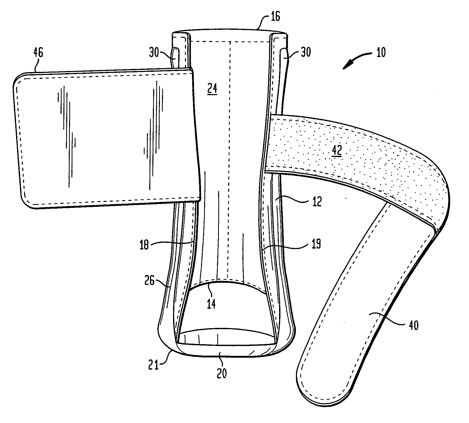
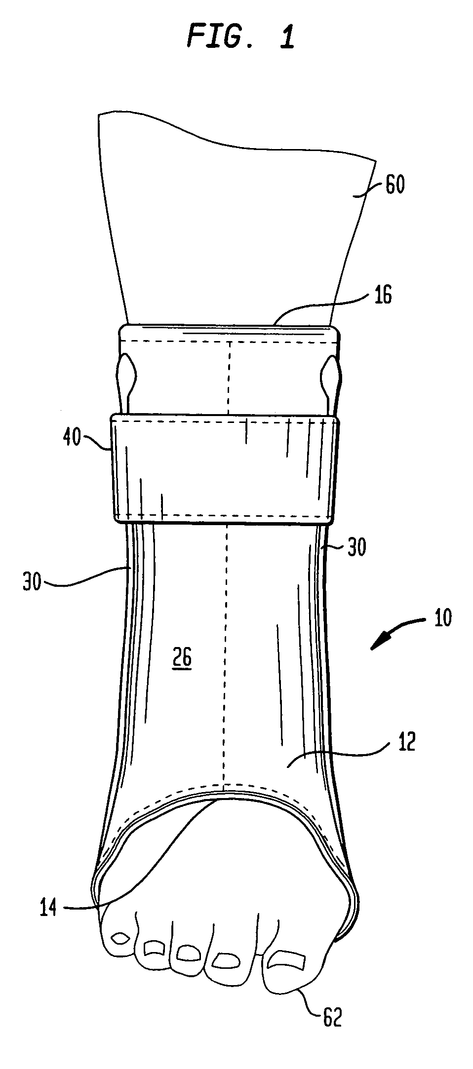
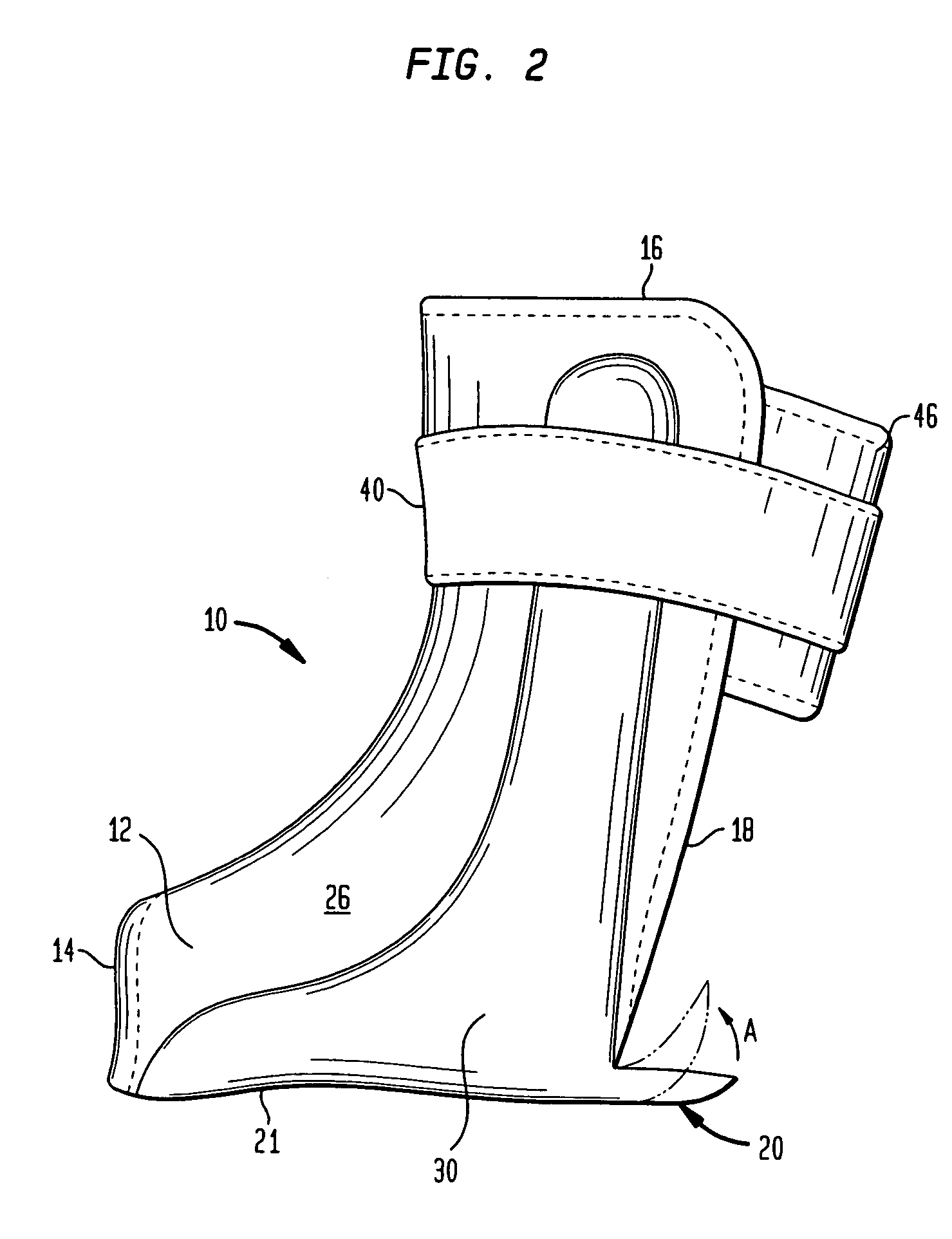
[0008] The present invention also provides a method for treating an ankle injury using the ankle brace of the invention. The method comprises custom forming a rigid member, incorporating the rigid member in a body having inner and outer layers, inserting a foot, toes first, between rear edges of a leg portion of the body; inserting the toes through a toe aperture; placing the foot onto a footbed portion; fastening a strap about the leg portion to secure the ankle brace to a foot and leg; and wearing the ankle brace on the leg for a sufficient time to treat the injury. The method further includes allowing the heel to flex to facilitate walking.
[0009] The present invention further provides an ankle brace having a support member sized to fit under a foot and extending upward along an ankle and leg of a wearer, inner and outer layers surrounding the support member and forming a compliant body having a foot portion and a leg portion, and an elongate strap for securing the brace to a wearer. The strap is attached at one end to an upper area of the foot portion, and is configured to be wrapped under the foot portion, up and across an ankle portion of the foot and around the leg portion, where it is removably attachable to the leg portion. The strap includes fastener for removably fastening the strap to the leg portion of the brace.

Problems solved by technology

Most are bulky and entirely rigid.
These devices are cumbersome and time-consuming to apply and diminish proprioception while ambulating because the heel is covered by the device.
Further, these devices are difficult to wear with standard footwear, leaving an individual self-consciously wearing only one shoe and an unsightly brace.

Method used


Image

  • Ankle brace
  • Ankle brace
  • Ankle brace

Examples


example

[0042] The ankle brace of the invention was tested on approximately 102 patients having the following conditions: 72 had posterior tibialis tendon dysfunction, 10 had Charcot ankles, 12 had Achilles injuries, and 8 had chronic ankle instability. The age range of the patients was 14 to 82 years with a mean age of 50. The patients were each fitted with a custom-molded ankle brace of the present invention. The patients wore the braces for approximately 12 hours per day. Patients were examined between 3 to 9 months (mean range 6 months), beginning from the time of first wearing the ankle brace of the present invention. The patients were asked questions about the status of their condition. All but two of the patients showed significant improvement in pain. Approximately 90% of the patients were successfully treated and did not require surgical intervention.

[0043] Referring to FIGS. 8-14, another embodiment of the ankle brace of the present invention, indicated generally at 110, is shown...


PUM


Abstract

A rear entry ankle brace for providing support and stability to an ankle includes a compliant support member covered on both sides by a flexible durable material. The ankle brace is flexible and compliant so as to fit a range of foot, ankle, and leg sizes, and is secured about a leg with a compliant strap. A flexible footbed heel is provided for facilitating walking. An elongate strap is provided for securing the brace to a wearer, wherein the strap is attached at one end to a foot portion of the brace, can be wrapped about the foot portion and a leg portion of the brace, and is removable attachable at an opposite end to the foot portion of the brace.

Description

RELATED APPLICATIONS [0001] The present application is a continuation-in-part of U.S. patent application Ser. No. 10 / 687,455 filed Oct. 16, 2003, now U.S. Pat. No. ______, the entire disclosure of which is expressly incorporated herein by reference.BACKGROUND OF THE INVENTION [0002] 1. Field of the Invention [0003] The present invention relates to an ankle brace device, and specifically to an ankle brace that is easily put on and minimizes interference with walking. [0004] 2. Related Art [0005] Ankle orthoses have become a standard treatment for orthopedic foot and ankle problems. Most are bulky and entirely rigid. Typically, a plurality of straps are required for attachment about the foot and ankle. These devices are cumbersome and time-consuming to apply and diminish proprioception while ambulating because the heel is covered by the device. Further, these devices are difficult to wear with standard footwear, leaving an individual self-consciously wearing only one shoe and an unsig...

Claims


Application Information

Patent Timeline
Patent Type & Authority Applications(United States)
IPC IPC(8): A61F5/00A61F13/06A61FA61F5/01
CPCA61F5/0111
Inventor RABE, DAVID
Owner RABE DAVID
Why Eureka
Try Eureka