Dual-function transmitting system

Inactive Publication Date: 2006-09-28
INTEREPOCH TECH
View PDF1 Cites 9 Cited by
  • Summary
  • Abstract
  • Description
  • Claims
  • Application Information

AI Technical Summary

Benefits of technology

[0013] The dual-function transmitting systems in first and second preferred embodiments are both integrated in existing CATV architectures and don't need much additional hardware. Accordingly, compared with prior arts, the dual-function transmitting systems according to this invention are convenient and inexpensive. The main differenc

Problems solved by technology

However, installing a plurality of APs not only cost a lot, but also increases the complexity of ne

Method used


Image

  • Dual-function transmitting system
  • Dual-function transmitting system
  • Dual-function transmitting system

Examples


Embodiment Construction

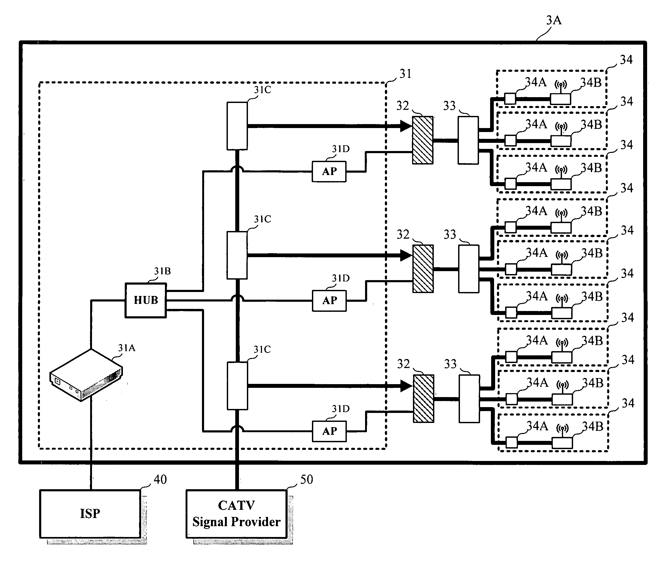
[0021] The main purpose of this invention is providing a dual-function transmitting system capable of transmitting CATV signals and wireless network signals simultaneously.

[0022] Please refer to FIG. 3. FIG. 3 shows the dual-function transmitting system according to the first preferred embodiment of this invention. The dual-function transmitting system 3A is integrated in the CATV architecture as shown in FIG. 2A. The dual-function transmitting system 3A includes a receiving module 31, N combining modules 32, N transmitting modules 33, and M signal providers 34. N and M are both natural numbers, and M is larger than or equal to N.

[0023] The receiving module is used for receiving the Ethernet signal provided by ISP 40 and the CATV signal provided by the CATV signal provider 50. The receiving module then transforms the Ethernet signal into a RF signal conforming to a wireless transmitting protocol, such as, IEEE 802.11a, IEEE 802.11b, or IEEE 802.11g. One thing to be noted is that i...


PUM


Abstract

A dual-function transmitting system is provided. The dual-function transmitting system includes a receiving module, N combining modules, N transmitting modules, and M signal providers. After receiving a CATV signal and an Ethernet signal, the receiving module transfers the Ethernet signal into a RF signal. Each of the N combining modules combines the CATV signal and the RF signal transferred from the receiving module to generate a combined signal, respectively. Each of the N transmitting modules is coupled to one corresponding combining module and transmits the combined signal received from the corresponding combining module. Each of the M signal providers is coupled to one corresponding transmitting module, receives the combined signal transmitted from the corresponding transmitting module, and provides the CATV signal and the RF signal comprised in the combined signal, respectively.

Description

BACKGROUND OF THE INVENTION [0001] 1. Field of the Invention [0002] This invention relates to a dual-function transmitting system. More specifically, this invention relates to a dual-function transmitting system capable of transmitting CATV signals and wireless network signals simultaneously. [0003] 2. Description of the Prior Art [0004] In recent years, networks have become important media for exchanging information. In contrast with wired networks, wireless networks further broaden the area where people can connect to the internet. [0005] Please refer to FIG. 1. FIG. 1 shows a general topology of how a wireless local area network (WLAN) is connected with the internet. The internet service provider (ISP) 10 provides channels for users to connect to the internet via ADSL / Cable modems and telephone lines / CATV cables. The access point (AP) 12 is used for transforming Ethernet signals into wireless network signals or transforming wireless network signals into Ethernet signals. The AP 1...

Claims


Application Information

Patent Timeline
IPC IPC(8): H04N7/18
CPCH04N21/23412H04N21/2665H04N21/6118H04H60/88H04H60/96
Inventor WU, HSI-MIEN B.LIU, CHIA-MING
Owner INTEREPOCH TECH
Why Eureka
Try Eureka