Exhaust gas purifying apparatus for internal combustion engine

a technology of exhaust gas purification apparatus and internal combustion engine, which is applied in the direction of machines/engines, output power, electric control, etc., can solve the problems of not being able to vaporize, increasing the possibility of poisoning the catalyst, and not being able to prevent the catalyst from being poisoned by sufficiently vaporizing an additiv

Active Publication Date: 2006-10-05
TOYOTA IND CORP +1
View PDF7 Cites 27 Cited by
  • Summary
  • Abstract
  • Description
  • Claims
  • Application Information

AI Technical Summary

Benefits of technology

[0005] Accordingly, it is an objective of the present invention to provide an exhaust gas

Problems solved by technology

However, when the light oil is added for a long period of time, the light oil that has not vaporized is absorbed by the active site of the catalyst.
However, if the light oil is supplied to the catalyst without being sufficiently vaporiz

Method used


Image

  • Exhaust gas purifying apparatus for internal combustion engine
  • Exhaust gas purifying apparatus for internal combustion engine
  • Exhaust gas purifying apparatus for internal combustion engine

Examples


Embodiment Construction

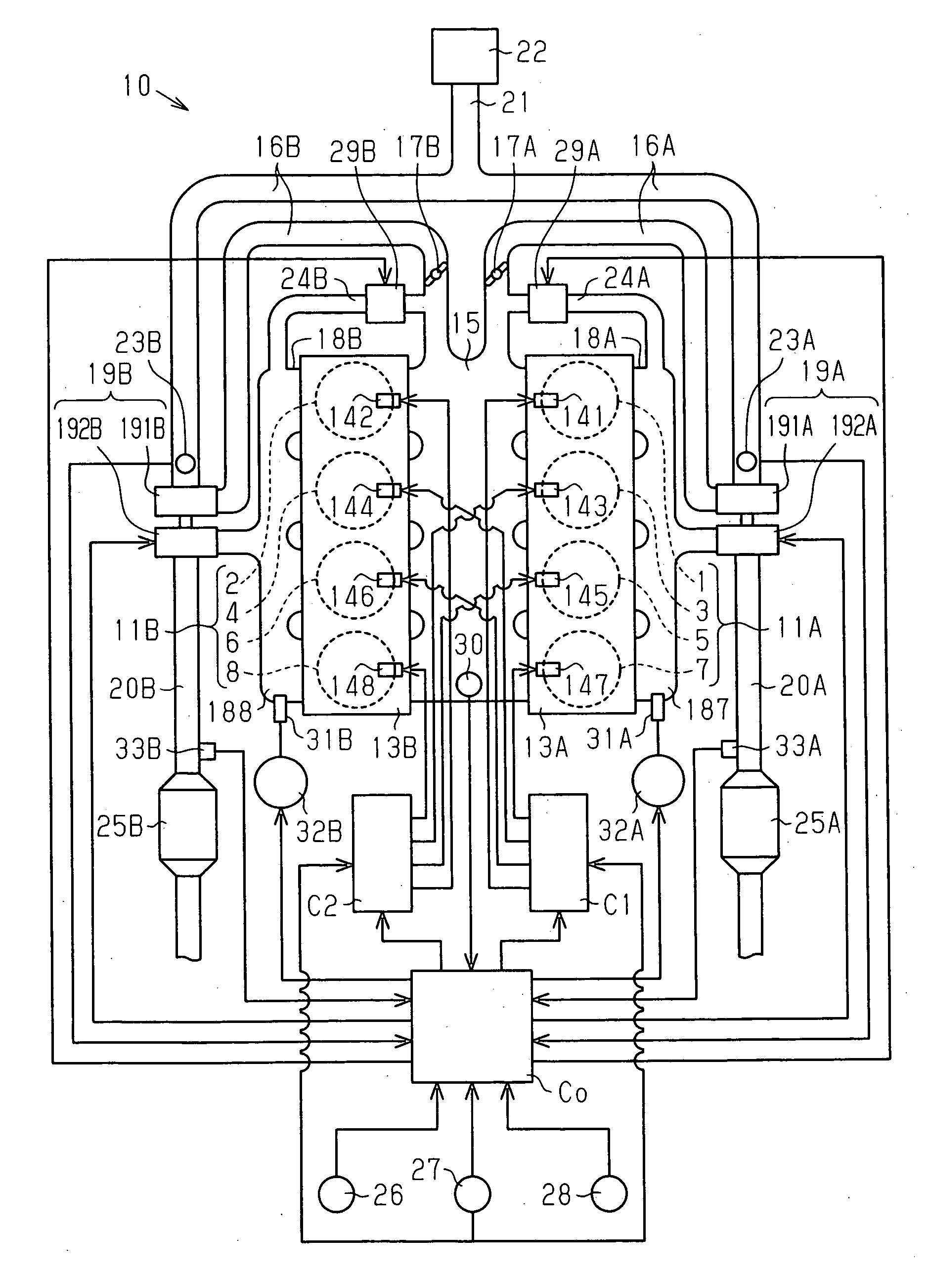
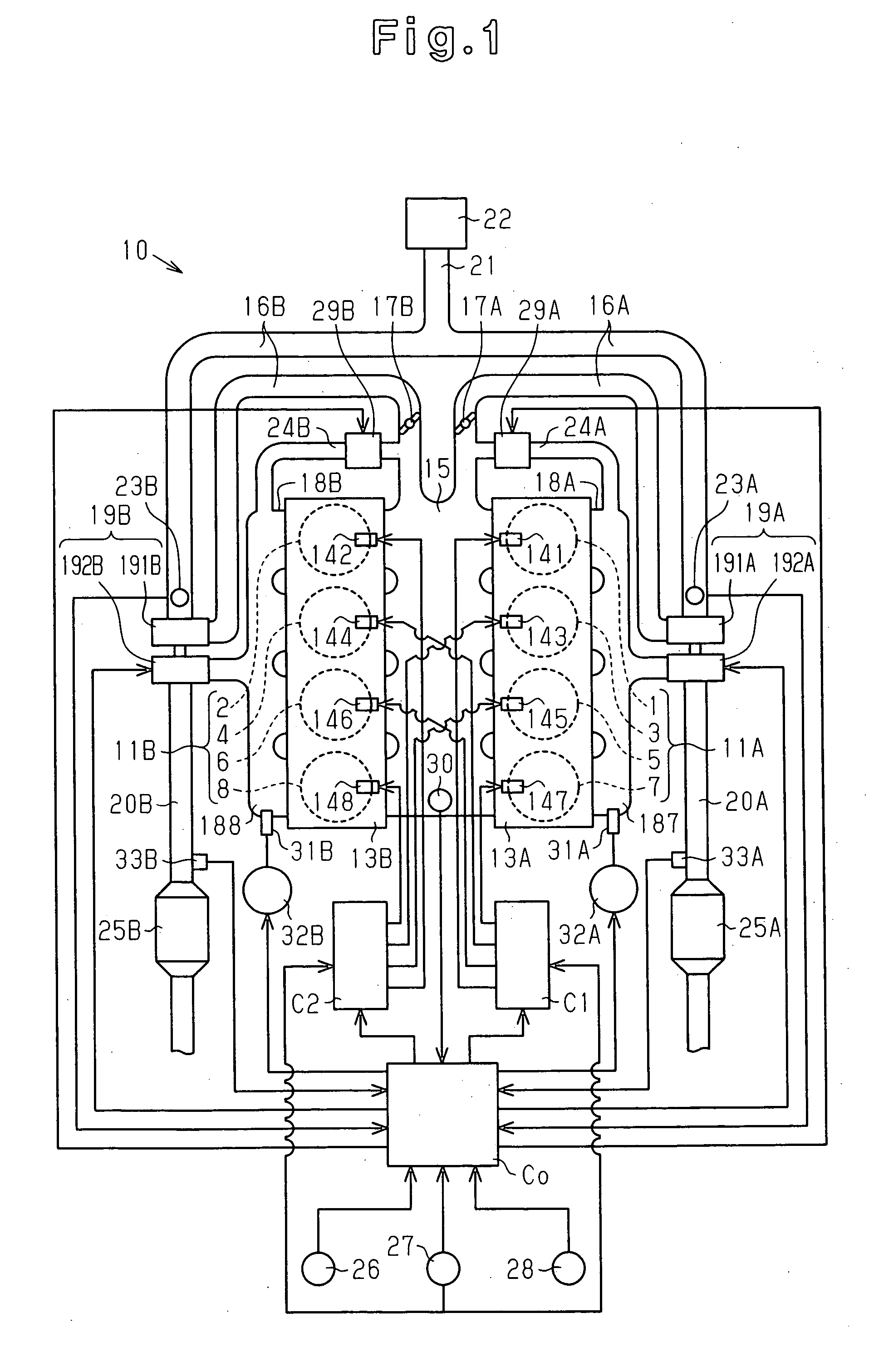
[0016] An exhaust gas purifying apparatus according to one embodiment of the present invention will now be described with reference to FIGS. 1 to 5. The exhaust gas purifying apparatus is mounted on a V-type 8-cylinder engine (4-cycle engine).

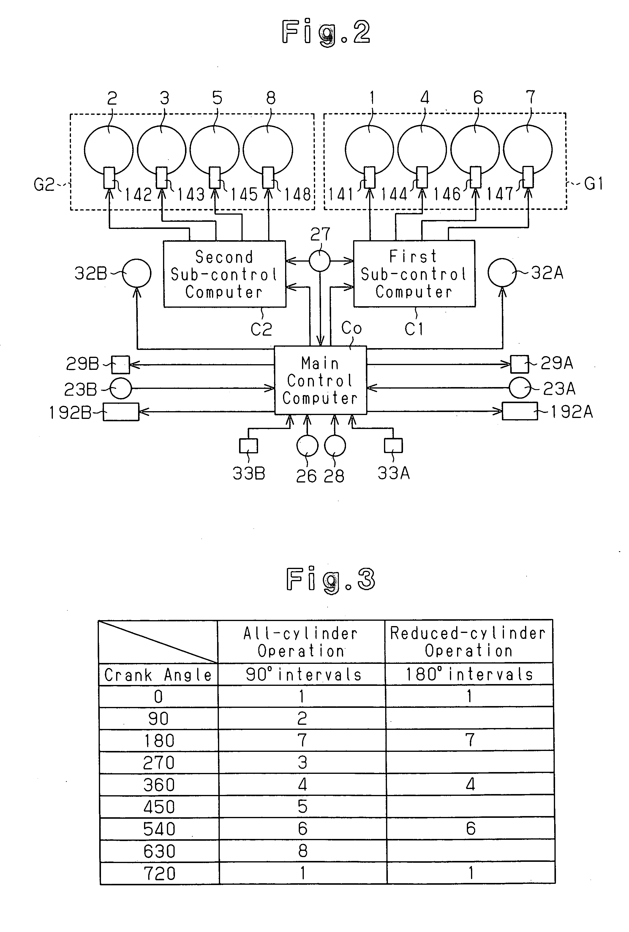
[0017] As shown in FIG. 1, a diesel engine 10 includes cylinders 1, 2, 3, 4, 5, 6, 7, 8. The cylinders 1 to 8 are divided into a first group 11A (the cylinders 1, 3, 5, 7) and a second group 11B (the cylinders 2, 4, 6, 8). Fuel injection nozzles 141, 143, 145, 147 are attached to a cylinder head 13A at positions corresponding to the cylinders 1, 3, 5, 7, respectively. Fuel injection nozzles 142, 144, 146, 148 are attached to a cylinder head 13B at positions corresponding to the cylinders 2, 4, 6, 8, respectively. The fuel injection nozzles 141 to 148 inject fuel (light oil) into the cylinders 1 to 8, respectively.

[0018] Intake ports (not shown) are formed in each of the cylinder heads 13A, 13B. The ends of the intake ports are connected to co...


PUM


Abstract

A main control computer commands a second sub-control computer to perform a reduced-cylinder operation when the coolant temperature detected by a coolant temperature sensor is greater than or equal to a reference temperature, and the exhaust temperature detected by a temperature sensor is less than a reference exhaust temperature and is within a reduced-cylinder operation allowable range in which a combination of the engine speed and the engine load is set in advance. The second sub-control computer deactivates a second cylinder group based on a command of the reduced-cylinder operation. The main control computer commands a first sub-control computer and the second sub-control computer to perform an all-cylinder operation when the coolant temperature detected by the coolant temperature sensor is less than the reference temperature, and the exhaust temperature detected by the temperature sensor is greater than or equal to the reference exhaust temperature or is out of the reduced-cylinder operation allowable range in which a combination of the engine speed and the engine load is set in advance.

Description

BACKGROUND OF THE INVENTION [0001] The present invention relates to an exhaust gas purifying apparatus for purifying exhaust gas of an internal combustion engine. [0002] In such an exhaust gas purifying apparatus, a catalyst arranged in an exhaust path of the engine purifies exhaust gas. For example, Japanese Laid-Open Patent Publication No. 11-294146 discloses measures for restoring the function of the catalyst for NOx (nitrogen oxides) when the catalyst is poisoned by HC (hydrocarbon). In the case of the above publication, NOx in the exhaust gas is purified by reacting with HC as the exhaust gas flows through the catalyst. For this reason, in a case of a diesel engine, since HC contained in exhaust gas is insufficient, fuel, which is light oil, is added to the catalyst to supplement the shortage of HC. However, when the light oil is added for a long period of time, the light oil that has not vaporized is absorbed by the active site of the catalyst. As a result, the catalytic activ...

Claims


Application Information

Patent Timeline
IPC IPC(8): F01N3/00F02D13/06F02D17/02
CPCF01N3/0821F01N13/011F01N3/0871F01N9/00F01N2560/06F01N2610/03F01N2900/08F02B37/007F02D17/02F02D41/0082F02D41/0087F02D41/0245F02D41/1446F02D41/266F02D2041/0012F02D2400/18F02M25/0711F02M25/0754Y02T10/26Y02T10/47F01N3/0842F02M26/08F02M26/47Y02T10/12Y02T10/40
Inventor NARITA, YUJITAKAHASHI, YOSHIYUKISUZUKI, HISANOBU
Owner TOYOTA IND CORP
Why Eureka
Try Eureka