Control valve for variable displacement compressor

a variable-discharge compressor and control valve technology, which is applied in the direction of positive-discharge liquid engines, machines/engines, lighting and heating apparatus, etc., can solve the problems of difficult to obtain a sufficient compression efficiency and inability to perform rotational speed control, and achieve the effect of enhancing compression efficiency inside the compressor

Inactive Publication Date: 2006-10-05
TGK
View PDF0 Cites 55 Cited by
  • Summary
  • Abstract
  • Description
  • Claims
  • Application Information

AI Technical Summary

Benefits of technology

[0013] The present invention has been made in view of the problem, and an object thereof is to enable a control valve for a variable displacement compressor, which operates by sensing a differential pressure between discharge pressure and suction pressure or between the discharge pressure and crankcase pressure, to enhance compression efficiency inside the compressor.
[0014] To solve the above problem, the present invention provides a control valve for a variable displacement compressor, which controls refrigerant displacement of the compressor by sensing a differential pressure between discharge pressure in a discharge chamber and suction pressure in a suction chamber or a differential pressure between the discharge pressure and crankcase pressure in a crankcase, comprising a first valve element that is fitted to and removed from a first valve hole communicating between the discharge chamber and the crankcase to thereby close and open the first valve hole, a second valve element that is fitted to and removed from a second valve hole communicating between the crankcase and the suction chamber to thereby close and open the second valve hole, and a solenoid that is capable of applying a force in a valve-opening direction to the second valve element via a shaft, thereby making it possible to cause the first valve element and the second valve element to move either independently of or in unison with each other, wherein after the first valve element closes the first valve hole, the second valve element opens the second valve hole.

Problems solved by technology

A compressor used in the refrigeration cycle of an automotive air conditioner, for compressing refrigerant, uses an engine as a drive source, and hence is incapable of performing rotational speed control.
This permits refrigerant introduced into the crankcase to be immediately delivered to make it difficult to obtain a sufficient compression efficiency.

Method used


Image

  • Control valve for variable displacement compressor
  • Control valve for variable displacement compressor
  • Control valve for variable displacement compressor

Examples


first embodiment

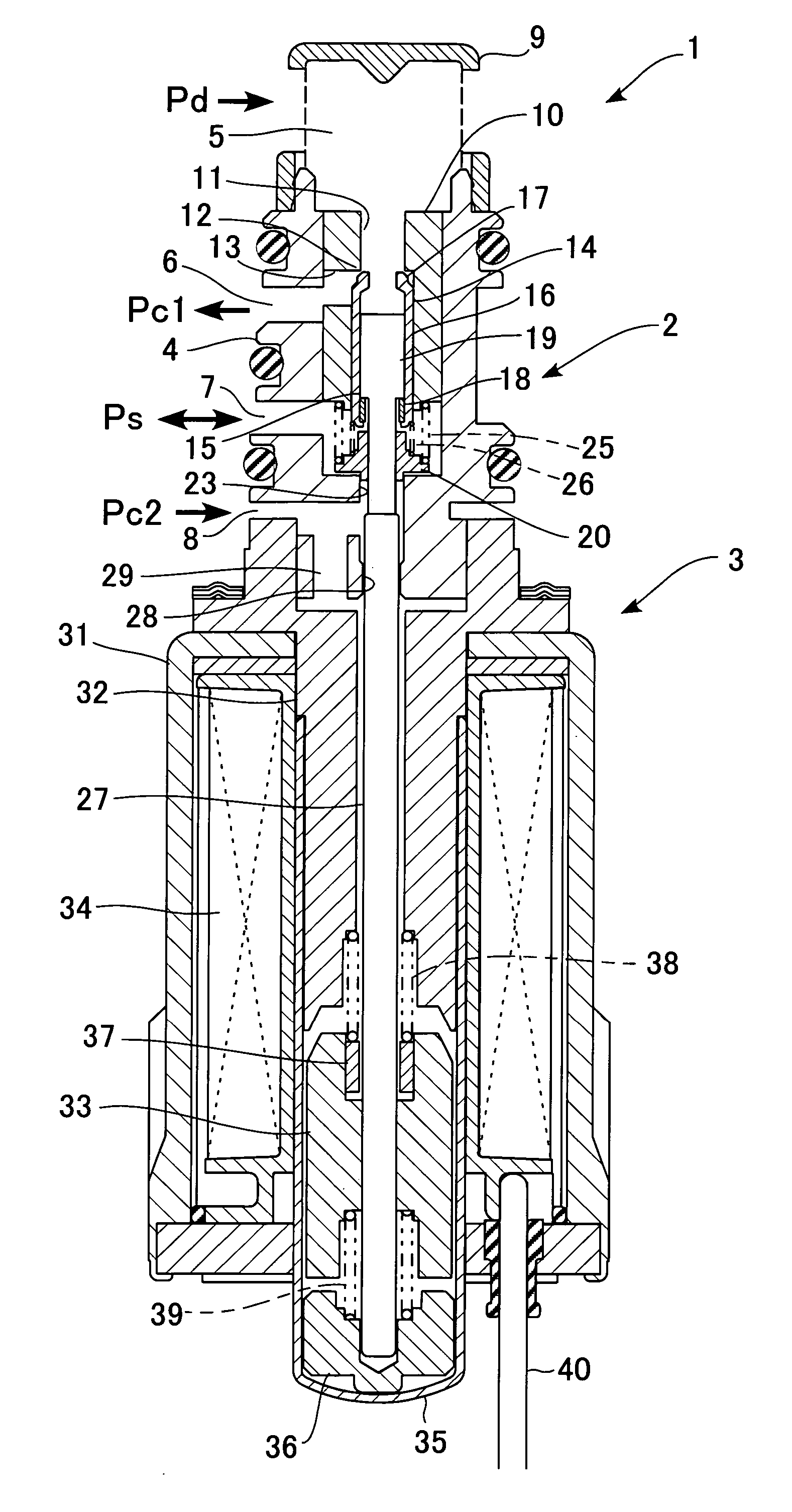
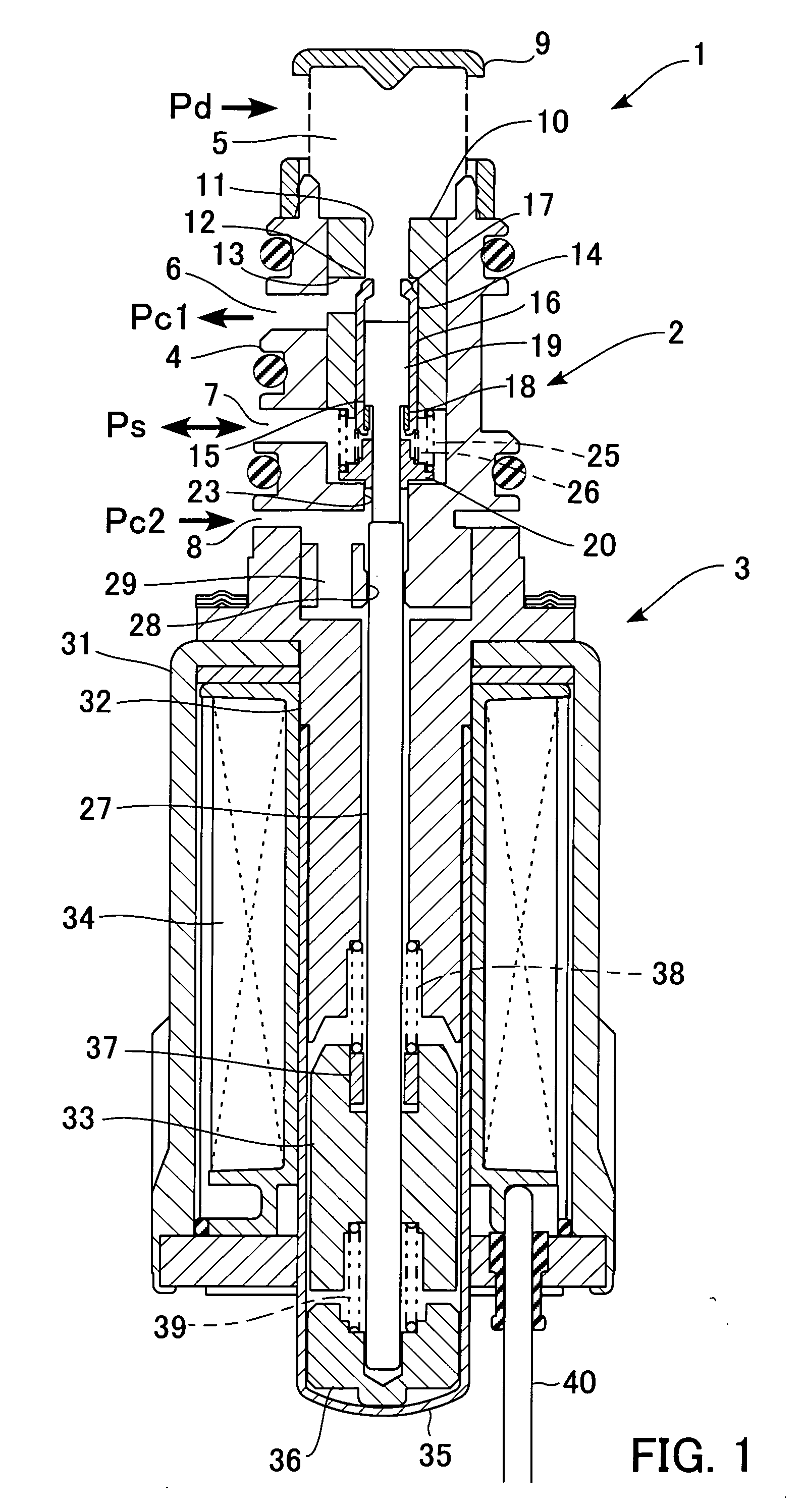
[0047]FIG. 1 is a cross-sectional view showing the construction of a control valve for a variable displacement compressor, according to a first embodiment of the present invention.

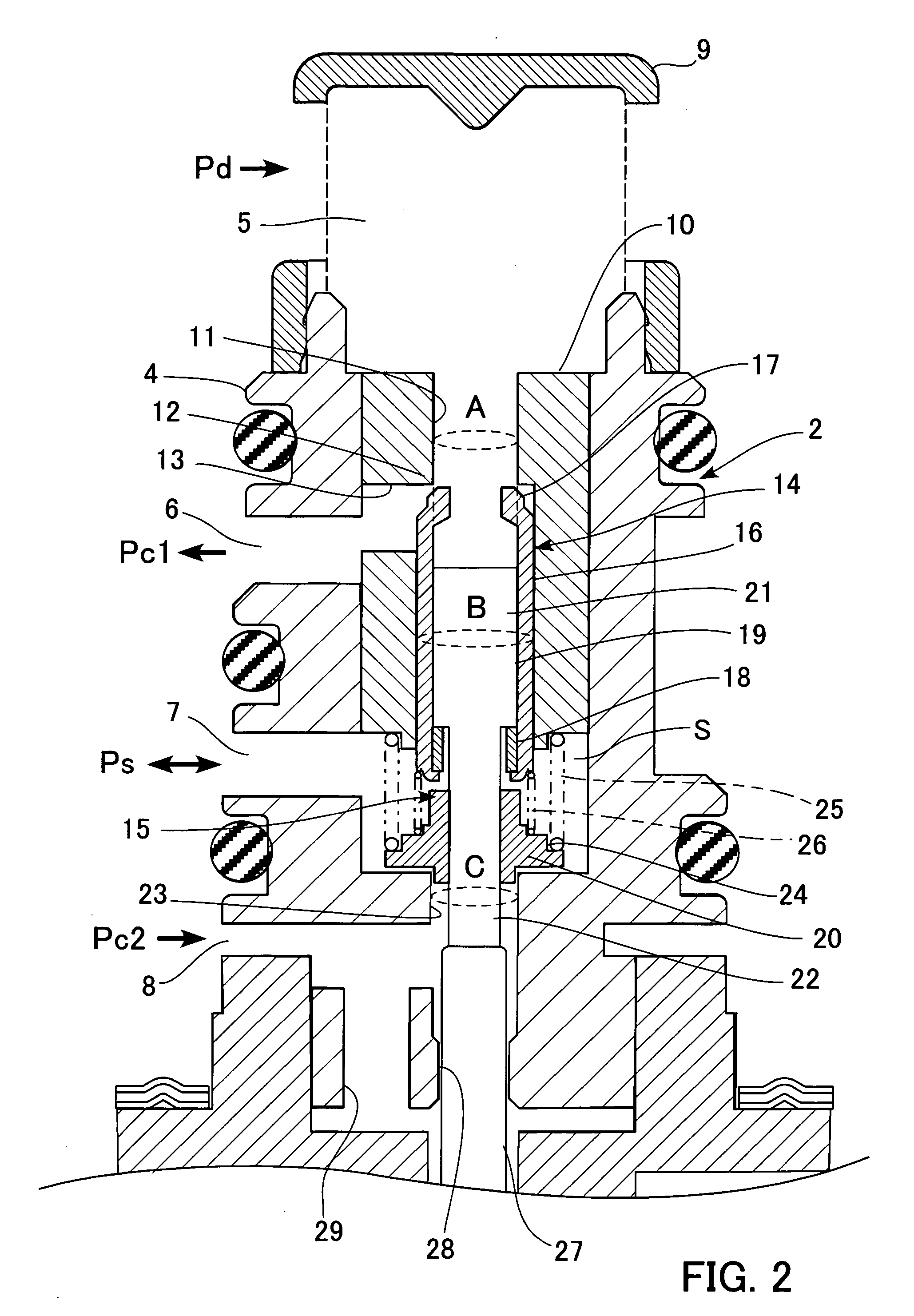
[0048] The control valve 1 is constructed by assembling a three-way valve 2 and a solenoid valve 3 into an integral unit. The three-way valve 2 opens and closes a refrigerant passage for introducing part of refrigerant in a discharge chamber of a variable displacement compressor, not shown, into a crankcase of the same, and a referent passage for delivering refrigerant in the crankcase to a suction chamber. Further, the solenoid valve 3 adjusts the opening degrees of the three-way valve 2 to thereby control the flow rates of refrigerant flowing through the refrigerant passages.

[0049] The three-way valve 2 has a body 4 in the form of a stepped hollow cylinder. The top of the body 4 is formed with a port 5 that communicates with the discharge chamber of the compressor to receive discharge pressure Pd there...

second embodiment

[0074] Next, a second embodiment of the present invention will be described. The control valve for a variable displacement compressor, according to the present embodiment, has substantially the same construction as that of the first embodiment except that the construction of the three-way valve is different. Therefore, component elements substantially identical to those of the first embodiment are designated by the same reference numerals, and description thereof is omitted as deemed appropriate. FIG. 5 is a cross-sectional view showing the construction of the control valve according to the present embodiment.

[0075] In the control valve 201 for a variable displacement compressor, a hollow cylindrical guide member 210 is fitted in an upper end opening of the body 204 of the three-way valve 202. The inner passage of a small-diameter portion of the guide member 210 forms a valve hole 211 (corresponding to “a first valve hole”), and the inner diameter of the valve hole 211 is smaller t...

third embodiment

[0087] Next, a third embodiment of the present invention will be described. The control valve for a variable displacement compressor, according to the present embodiment, has substantially the same construction as that of the first embodiment except that the construction of the three-way valve is different. Therefore, component elements substantially identical to those of the first embodiment are designated by the same reference numerals, and description thereof is omitted as deemed appropriate. FIG. 7 is a cross-sectional view showing the construction of the control valve according to the present embodiment.

[0088] In the control valve 301 for a variable displacement compressor, a guide member 310 in the form of a hollow cylinder is fitted in an upper end opening of a body 304 of a three-way valve 302. A small-diameter portion of the guide member 310 has a valve element 314 (corresponding to “a first valve element”) axially slidably inserted therein, and the internal passage of the...


PUM


Abstract

To enable a control valve for a variable displacement compressor, which operates by sensing a differential pressure between discharge pressure and suction pressure or between the discharge pressure and crankcase pressure, to enhance compression efficiency inside the compressor. In the control valve for a variable displacement compressor, according to the present invention, after a valve element on a high pressure side closes a valve hole, a valve element on a low pressure side opens a valve hole. Therefore, it is possible to eliminate a region in which both the valves on the high pressure side and the low pressure side are simultaneously open. This makes it possible to prevent refrigerant introduced into a crankcase from being immediately delivered, which makes it possible to obtain a sufficient compression efficient.

Description

CROSS-REFERENCE TO RELATED APPLICATIONS [0001] This application claims priority of Japanese Applications No. 2005-104409 filed on Mar. 31, 2005 and entitled “control valve for variable displacement compressor”, and No. 2005-337480 filed on Nov. 22, 2005 and entitled “control valve for variable displacement compressor”. BACKGROUND OF THE INVENTION [0002] 1) Field of the Invention [0003] The present invention relates to a control valve for a variable displacement compressor, and more particularly to a control valve for a variable displacement compressor, for controlling the displacement of the compressor as a component of a refrigeration cycle of an automotive air conditioner. [0004] 2) Description of the Related Art [0005] A compressor used in the refrigeration cycle of an automotive air conditioner, for compressing refrigerant, uses an engine as a drive source, and hence is incapable of performing rotational speed control. To eliminate the inconvenience, a variable displacement comp...

Claims


Application Information

Patent Timeline
Patent Type & Authority Applications(United States)
IPC IPC(8): F25B49/00F16K31/02
CPCF04B27/1804F04B2027/1854F04B2027/1831F04B2027/1827F04B27/14F04B49/00
Inventor HIROTA, HISATOSHI
Owner TGK
Why Eureka
Try Eureka