Hypoid gear device

Inactive Publication Date: 2006-10-05
THK CO LTD
View PDF21 Cites 10 Cited by
  • Summary
  • Abstract
  • Description
  • Claims
  • Application Information

AI Technical Summary

Benefits of technology

[0016] According to the invention of this claim 4, since the driving pinion rotates the driven wheel in one direction and, at this moment, the driven pinion slips, by the actuation of the friction clutch, and then urges the driven wheel in the reverse direction, the driving pinion contacts one tooth flank of the driven wheel and, at the same time, the driven pinion always contacts the other side tooth flank of the driven wheel, thereby eliminating the backlash.
[0017] Furthermore, the invention of claim 5 provides a hypoid gear device provided with a backlash eliminating unit for eliminating a backlash between a driven wheel and a driving pinion meshed with the driven wheel, the driven wheel being supported to be rotatable with a shaft thereof and to be slidable thereon, and the backlash eliminating unit comprising an elastic memb

Problems solved by technology

In the hypoid gear device, backlash exists as like as in a usual gear, and for example, in the presence of the backlash, an indexing error is caused at a time of indexing a worktable.
However, it is difficult to substantially eliminate the backlash by baking and grinding the hypoi

Method used


Image

  • Hypoid gear device
  • Hypoid gear device
  • Hypoid gear device

Examples


Example

First Embodiment 1

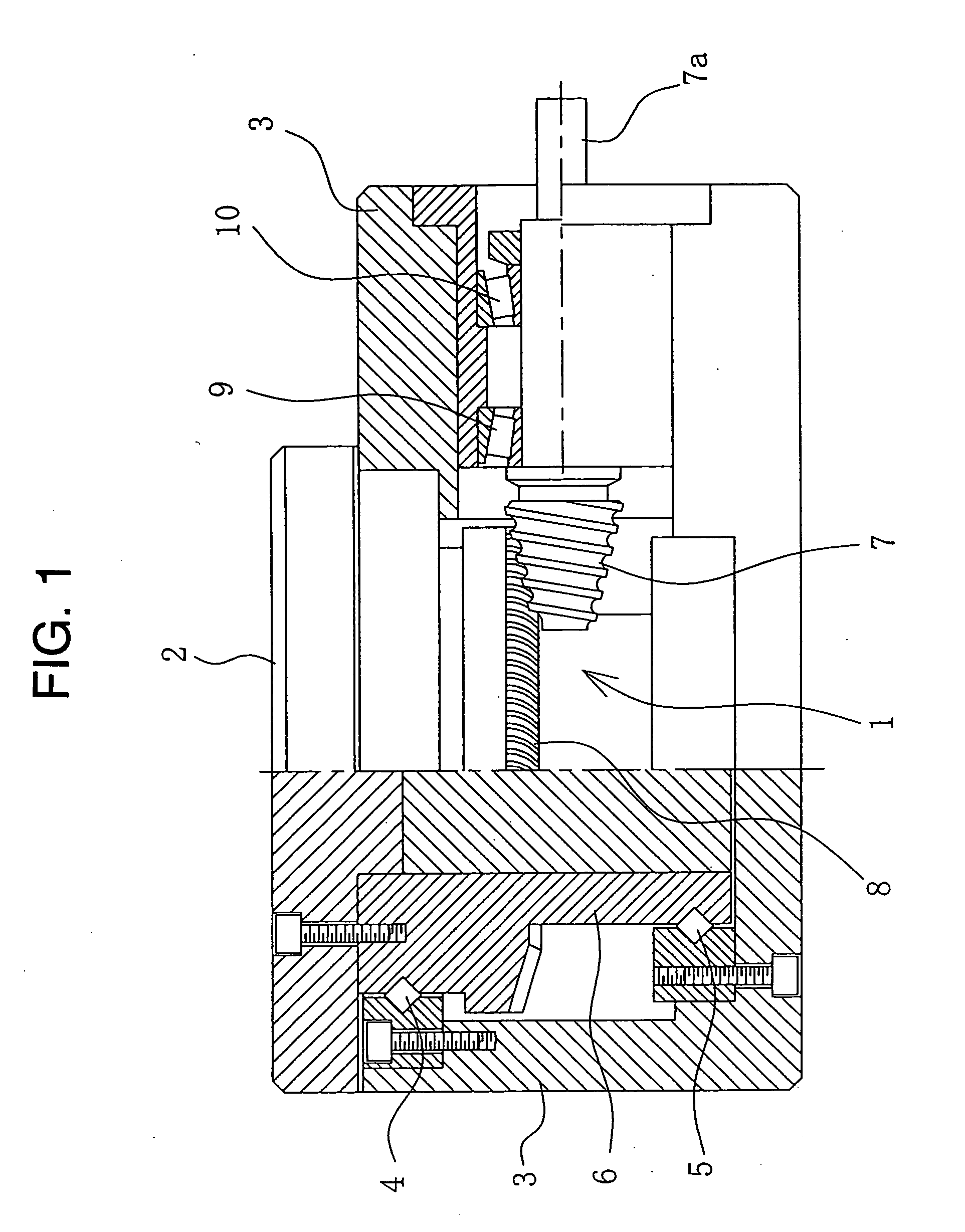
[0036] As shown in FIG. 1, a hypoid gear device 1 is used as transmission or gearing for rotating a work table 2 of a table device.

[0037] This work table 2 is for fixing a work, not shown, to be worked by a machine tool, in which the work table 2 is fixed to an upper end portion of a rotating shaft 6 supported vertically to a machine frame 3 through various kinds of bearings 4, 5.

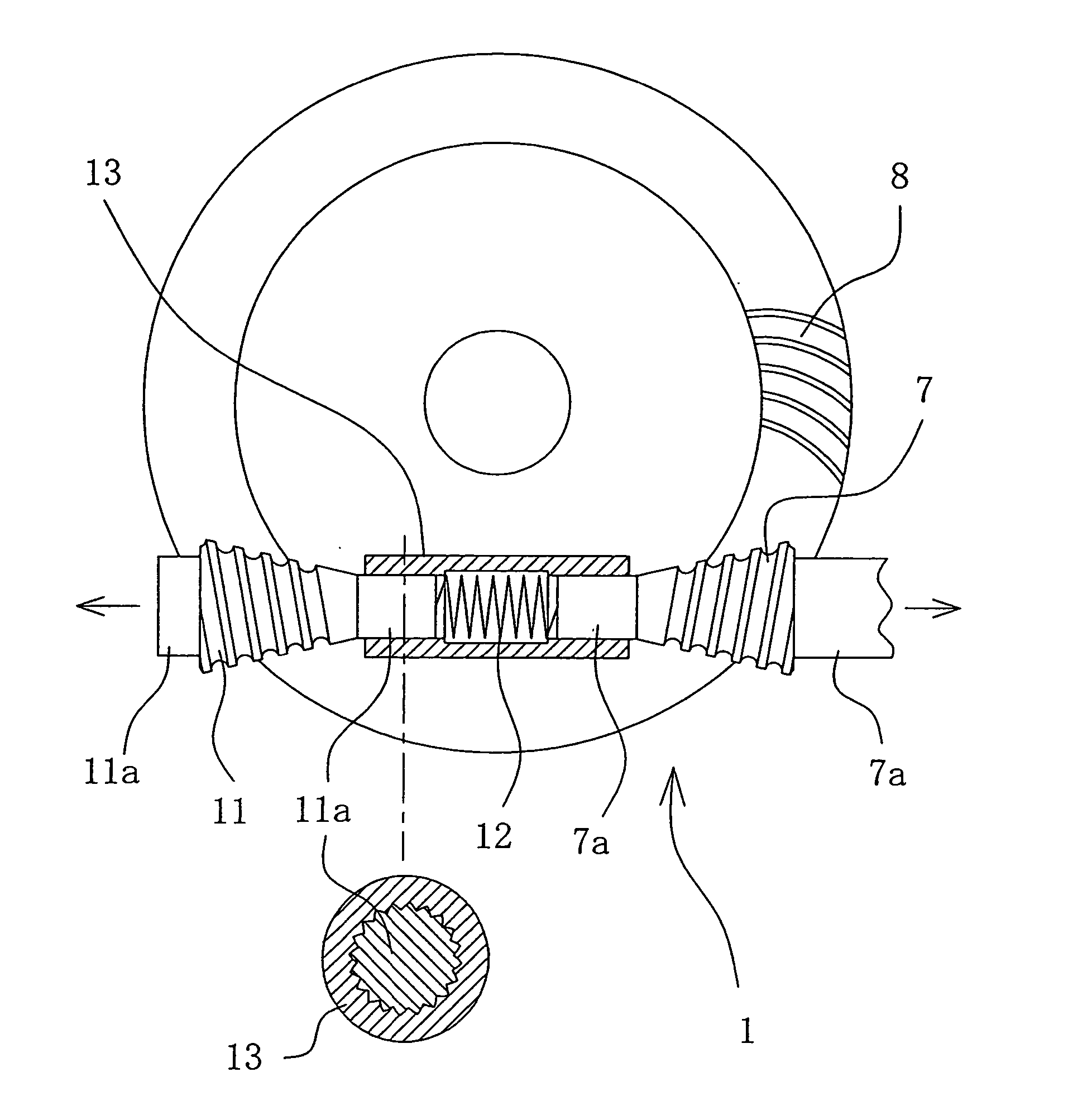
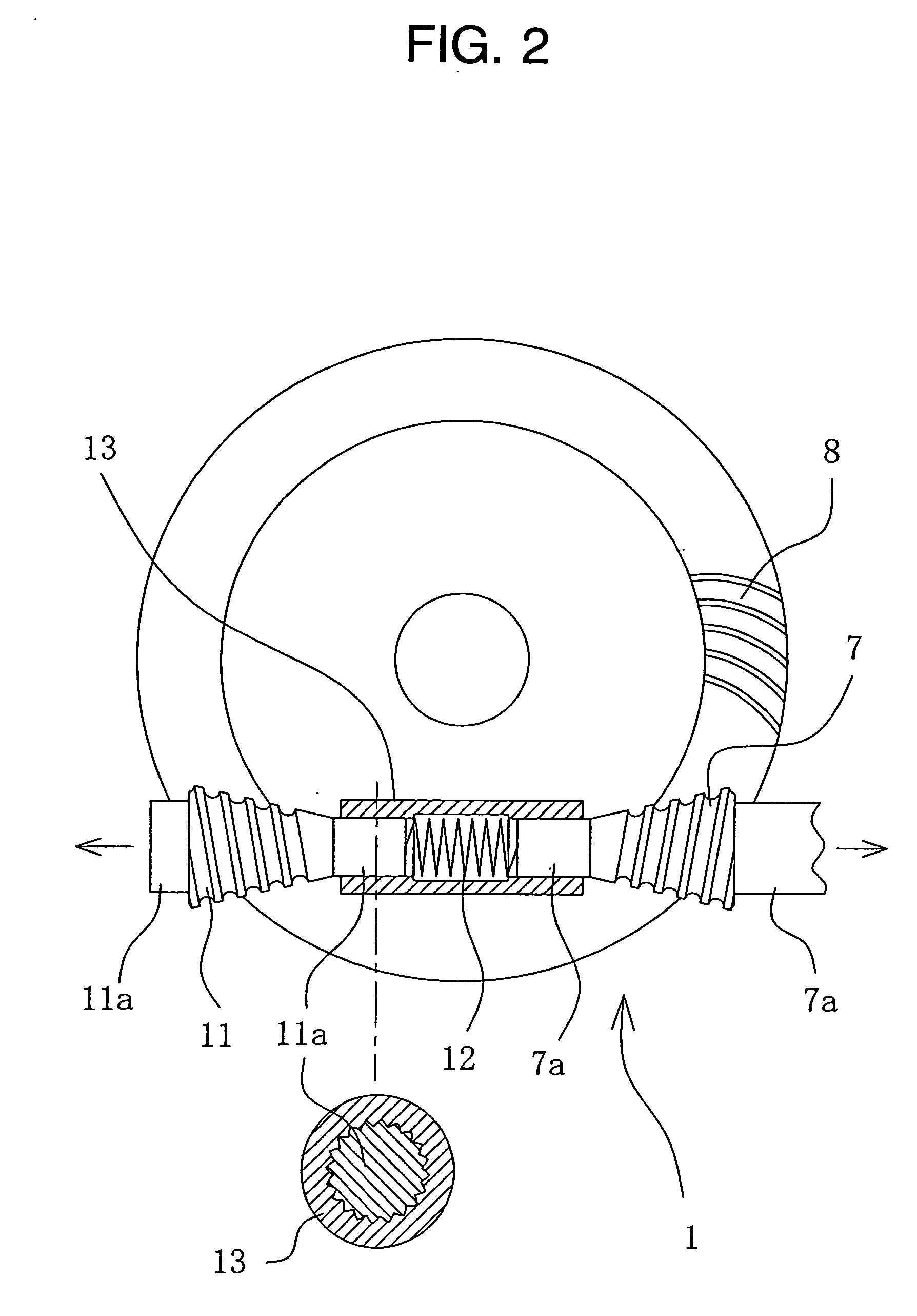
[0038] As shown in FIGS. 1 and 2, the hypoid gear device 1 is composed of a driving small gear (i.e., pinion) 7 and a driven large gear (i.e., wheel) 8. The wheel 8 is fixed to a lower surface of the work table 2 so that the axis of the wheel 8 accords with that of the rotating shaft 6, and a shaft 7a of the pinion 7 is supported horizontally by way of the various kinds of bearings 9, 10.

[0039] When a control motor, not shown, is driven, the rotation of the motor is transmitted to the drive pinion 7 to the driven wheel 8 and then to the work table 2, which is then stopped after rotatin...

Example

Second Embodiment 2

[0047] A hypoid gear device 14 according to the second embodiment 2 of the present invention differs from the first embodiment 1, as shown in FIGS. 3A and 3B, in that the backlash eliminating means of this second embodiment 2 is provided with a driven wheel 15 composed of a plurality of ring members 15a, 15b divided in its radial direction and a plate spring 16, as elastic member, for twisting the plural ring members 15a, 15b in directions opposing to each other.

[0048] More specifically, the driven wheel 15 is divided in its radial direction into inner and outer ring members 15a and 15b, which are fitted to each other so as to be relatively rotatable about the axis thereof.

[0049] The plate spring 16, as elastic member, is bent in form of ring. As shown in FIG. 3B, an annular accommodation chamber 17 for accommodating therein the plate spring 16 is formed at a boundary portion between the inner and outer ring members 15a and 15b of the driven wheel 15, and as sh...

Example

[0050] As described above, according to the arrangement of this second embodiment, the inner and outer ring members 15a and 15b of the driven wheel 15 are twisted around the axis thereof in the directions opposing to each other by the plate spring 16, as elastic member, the opposing teeth flanks of the driven wheel 15 simultaneously contact the teeth of the driving pinion 7, thereby eliminating the backlash. In addition, by the elastic force of the plate spring 16 as elastic member in its twisting direction, a preload in substantially the tangential direction to the tooth flank of the driven wheel 15 is applied to the driven wheel 15, thereby suppressing the increasing in the backlash due to the wearing of the tooth flanks.

[0051] Further, the same reference numerals are applied to the portions or elements of the hypoid gear device 1 of this second embodiment 2 corresponding to those of the first embodiment 1, and repeated description is omitted herein.


PUM


Abstract

A hypoid gear device is provided with a backlash eliminating unit arranged between a driven wheel and a driving pinion to be meshed with the driven wheel. The backlash eliminating unit includes a driven pinion mounted on the same shaft as that of the driving pinion so as to be meshed with the driven wheel, and an elastic member urging the driven pinion on the same shaft of the driving pinion in the direction reverse thereto.

Description

TECHNICAL FIELD [0001] The present invention relates to a hypoid gear device. BACKGROUND ART [0002] A hypoid gear device is adopted for transmitting rotation quietly and smoothly in comparison with a spiral gear by applying a sliding motion in a tooth trace direction to a rolling motion in the spiral gear and is utilized for driving of an axle of an automobile, rotation of a worktable of a machine tool, and the like (for example, refer to the following Patent Publications 1, 2 and 3). [0003] In the hypoid gear device, backlash exists as like as in a usual gear, and for example, in the presence of the backlash, an indexing error is caused at a time of indexing a worktable. Then, in a prior art, such backlash has been eliminated by baking and grinding the hypoid gear device and then working it with high performance (for example, refer to the following Patent Publications 1 and 2). Moreover, such backlash has been eliminated by urging a small gear meshed with a large gear in an axial d...

Claims


Application Information

Patent Timeline
IPC IPC(8): F16H57/00F16H1/14F16H1/20F16H55/20F16H55/24F16H57/12
CPCF16H1/145F16H55/24Y10T74/19633F16H2057/121F16H57/12
Inventor MICHIOKA, HIDEKAZUTAMANO, MASAHIKOIMAMURA, MASAYUKISHIRAI, TAKEKIYATSUSHIRO, DAISUKE
Owner THK CO LTD
Why Eureka
Try Eureka