

Manipulator
a manipulator and manipulating rod technology, applied in the field of manipulators, can solve the problems of complicated structure and complicated wiring, and achieve the effect of simplifying structure and increasing freedom
- Summary
- Abstract
- Description
- Claims
- Application Information
AI Technical Summary
Benefits of technology
Problems solved by technology
Method used
Image

Examples
first embodiment
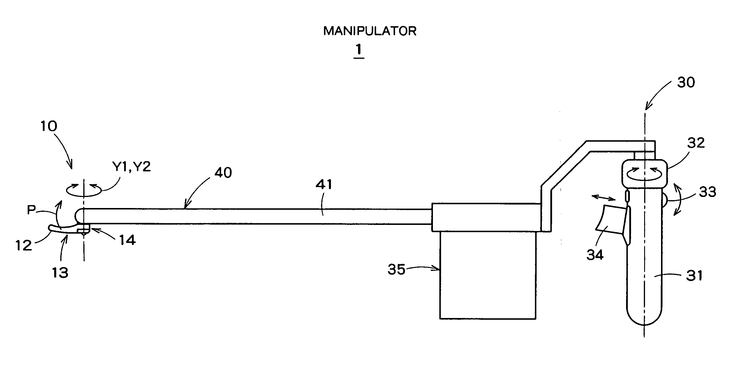
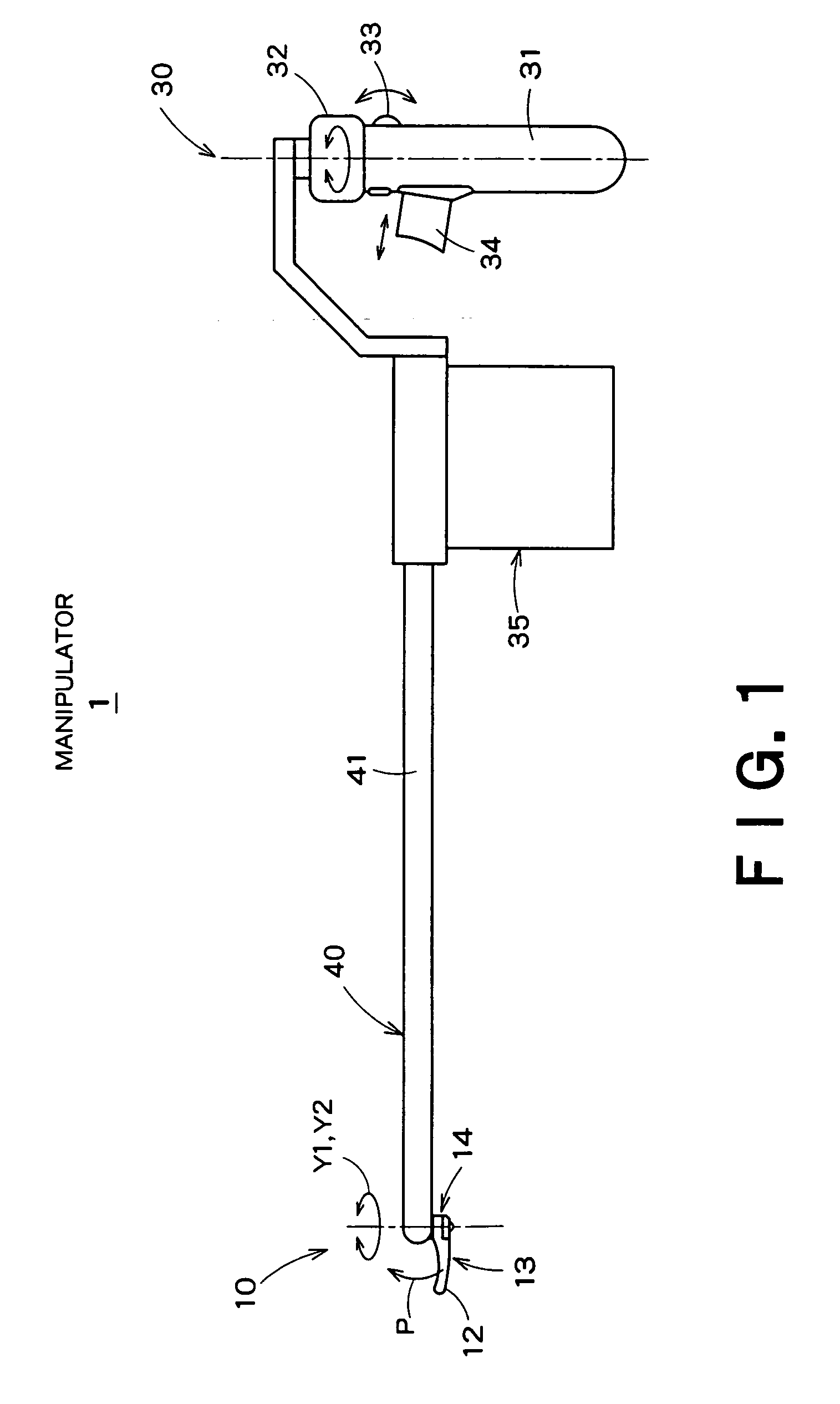
[0123] As shown in FIG. 1, a manipulator 1 according to a first embodiment of the present invention is used for, for example, laparoscopic surgeries, and includes an operating portion 10 that treats an affected part, a manipulating portion 30 that receives input manipulations controlling the operation of the operating portion 10, and a connecting portion 40 that connects the operating portion 10 and the manipulating portion 30 together.
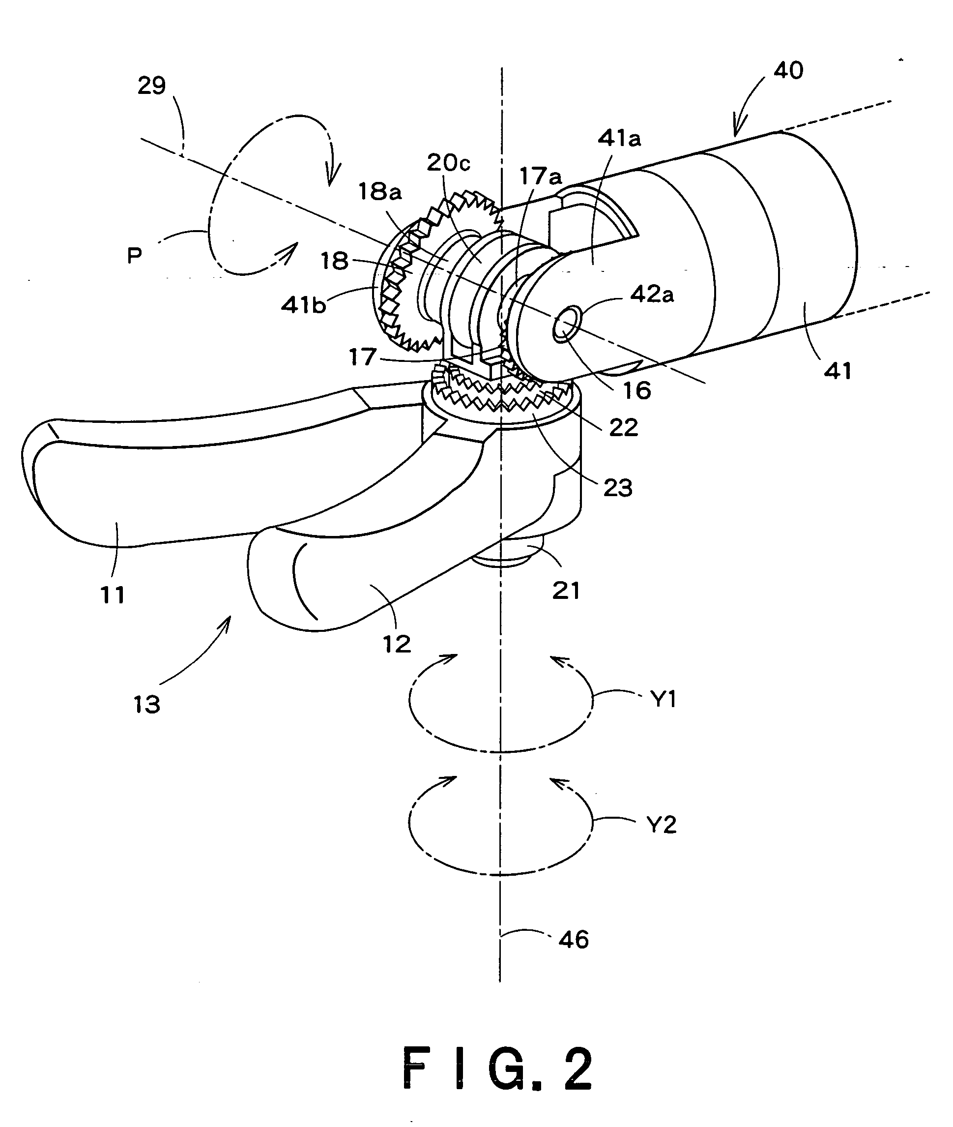
[0124] As shown in FIGS. 2 and 3, the manipulator 1 includes a first rotor shaft 16 (rotor axis 29) which crosses to a direction along a longitudinal direction of the connecting portion 40 at a tip of which a treating portion (operating portion 10) is provided to treat a treatment target, a main shaft 20 supported rotatably in a direction around the first rotor shaft 16, which has a main shaft portion 20b arranged orthogonal to the first rotor shaft 16, a first gear 17 supported rotatably in the direction around the first rotor shaft 16, a second gea...
second embodiment
[0164] A manipulator 1 according to a second embodiment of the present invention includes a gripping forceps 13 serving as a first treating tool portion and a scissor forceps 53 serving as a second treating tool portion in the operating portion 10, as shown in FIG. 15 where components corresponding to those in FIG. 3 are shown by the same reference numerals.
[0165] As shown in FIGS. 16 and 17, the scissor forceps 53 are provided opposite to the gripping forceps 13 by sandwiching the support portions 11b and 12b. A cutting edge portion 54 of the scissor forceps 53 is integrated with the gripper 11. A cutting edge portion 55 of the scissor forceps 53 is integrated with the gripper 12. This enables the scissor forceps 53 to be opened or closed by rotating the gears 17 and 18 to open or close the grippers 11 and 12.
[0166] With the manipulator 1 configured as described above, the gripping forceps 13 and the scissor forceps 53 can be switched by rotating the two types of forceps in the p...
third embodiment
[0175] A manipulator 100 in accordance with a third embodiment of the present invention is shown in FIGS. 25, 26 and 27 where components corresponding to those in FIGS. 2, 3, and 4 are denoted by the same reference numerals. The manipulator 100 includes the first rotor shaft 16 (rotor axis 29) arranged orthogonal to a direction extending along the longitudinal direction of the connecting portion 40 at a tip of which a treating portion is provided to treat a treatment target, a main shaft 120 which is rotatably supported around the rotor shaft 16 and has a main shaft portion 120b (main axis 46) orthogonal to the rotor shaft 16, a first gear 117 rotatably supported around the first rotor shaft 16, a second gear 121a which engages with the first gear 117 at a state orthogonal to the first gear 117 and is rotatably supported in a direction around the main shaft portion 120b, a third gear 121b which rotates coaxially and together with the second gear 121a, a fourth gear 123 that engages ...
PUM
 Abstract
Description
Claims
Application Information