
Hydraulic fracturing

a technology of hydraulic fracturing and fracturing chamber, which is applied in the field of hydraulic fracturing, can solve the problems of inability to produce accurate real time information, limited direct measurement capability of operators,

Inactive Publication Date: 2006-10-05
COMMONWEALTH SCI & IND RES ORG
View PDF2 Cites 47 Cited by
  • Summary
  • Abstract
  • Description
  • Claims
  • Application Information

AI Technical Summary

Benefits of technology

[0017] The method may further comprise deriving from the comparison of the estimated and actual tilt changes useful values for initially undetermined values of parameters of the model.
[0018] The useful values of said parameters may be estimated using an inverse procedure.

Problems solved by technology

One of the most important issues in the practice of the hydraulic fracturing technique is knowledge of the geometry (orientation, extent, volume) of the created fracture.
However, operators presently have only limited direct measurement capability that allows them to verify the quality and effectiveness of their operations.
In order to map hydraulic fractures, several types of indirect measurements can be carried out such as microseismic acoustic monitoring and tiltmeter mapping, but until recently such surface tiltmeter techniques have not been capable of producing accurate real time information which can be used during the course of a hydraulic fracturing treatment and have generally been used to provide data for later analysis.

Method used


Image

  • Hydraulic fracturing
  • Hydraulic fracturing
  • Hydraulic fracturing

Examples


an example

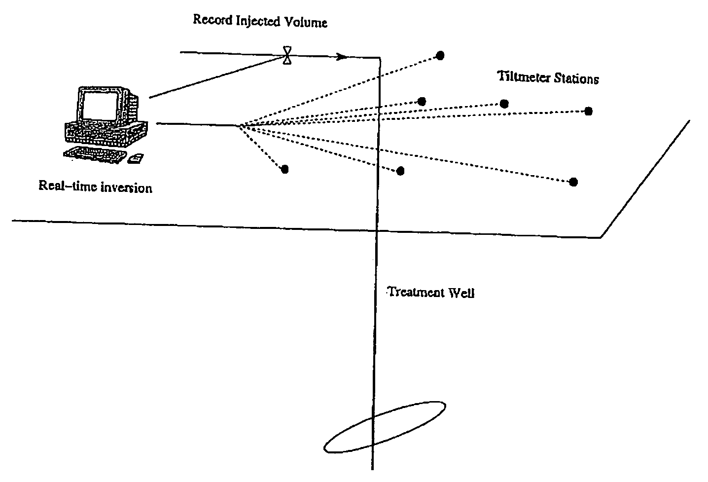
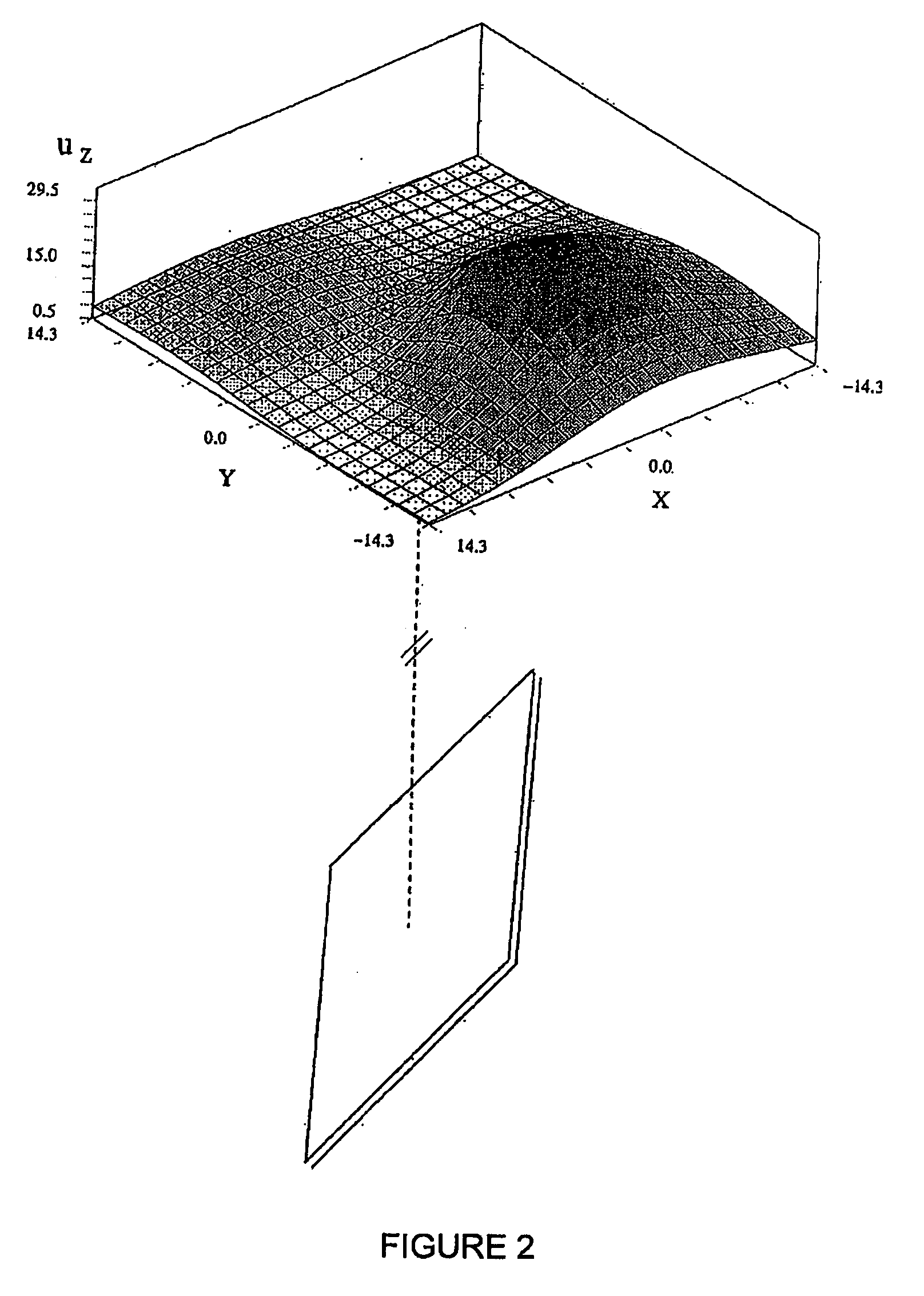
[0060] As an illustrating example, let consider the following synthetic case. The tiltmeter data corresponding to the growth of a Hydraulic Fracture of so-called PKN geometry (with coefficients α=2, β=2e−3, see eqns (1)-(2)) . . . are simulated and noise is added to this synthetic data set. The data are logged by a borehole array located 200 meters from the fracture (a far-field array). Tilts are sampled every minute. The synthetic data are then inverted using the same PKN model for the fracture growth model (see eqns. (1)-(2)). The parameters (α,β) are supposed unknowns and are retrieved via an inverse calculation using the simulated tilt data. The values of both parameters are retrieved accurately, we obtain α=1.94, β=1.98e−3. The fit of the tilt data at a particular tilt station can be seen in FIG. 6. FIG. 5 shows the time evolution fracture half-length and aperture at the fracture center obtained from eq. and the estimated values of the coefficients α and β. The estimated values...


PUM


Abstract

Method and apparatus for monitoring growth of fracture during hydraulic fracturing treatment of a ground formation. A series of tiltmeters are positioned at spaced apart tiltmeter stations at which tilt changes due to hydraulic fracturing treatment are measurable by those tiltmeters. Tilt measurements obtained from the tiltmeters at progressive times during the fracture treatment are compared with estimated tilt changes estimated from an assumed hydraulic fracturing propagation. Useful values for initially undetermined values of parameters of the model are derived using an inverse procedure. The data analysis may be performed in real time as the hydraulic treatment progresses using differing propagation models to determine a most probable model.

Description

TECHNICAL FIELD [0001] This invention relates to hydraulic fracturing of natural ground formations which may be on land or under a sea bed. [0002] Hydraulic fracturing is a technique widely used in the oil and gas industry in order to enhance the recovery of hydrocarbons. A fracturing treatment consists of injecting a viscous fluid at sufficient rate and pressure into a bore hole drilled in a rock formation such that the propagation of a fracture results. In later stages of the fracturing treatment, the fracturing fluid often contains a proppant, typically sand, so that when the injecting stops, the fracture closes on the proppant which then forms a highly permeable channel (compared to the permeability of the surrounding rock) which may thus enhance the production from the bore hole or well. [0003] In recent years, hydraulic fracturing has been applied for inducing caving and for preconditioning of rock for caving in the mining industry. In this application, the fractures are typic...

Claims


Application Information

Patent Timeline
Patent Type & Authority Applications(United States)
IPC IPC(8): E21B47/02E21B43/26E21B47/00
CPCE21B43/26E21B49/00E21B47/02
Inventor LECAMPION, BRICE TANGUY ALPHONSE
Owner COMMONWEALTH SCI & IND RES ORG
Learn More