
Techniques for facilitating identification updates in an integrated circuit

Inactive Publication Date: 2006-10-05
AGERE SYST INC
View PDF3 Cites 5 Cited by
  • Summary
  • Abstract
  • Description
  • Claims
  • Application Information

AI Technical Summary

Benefits of technology

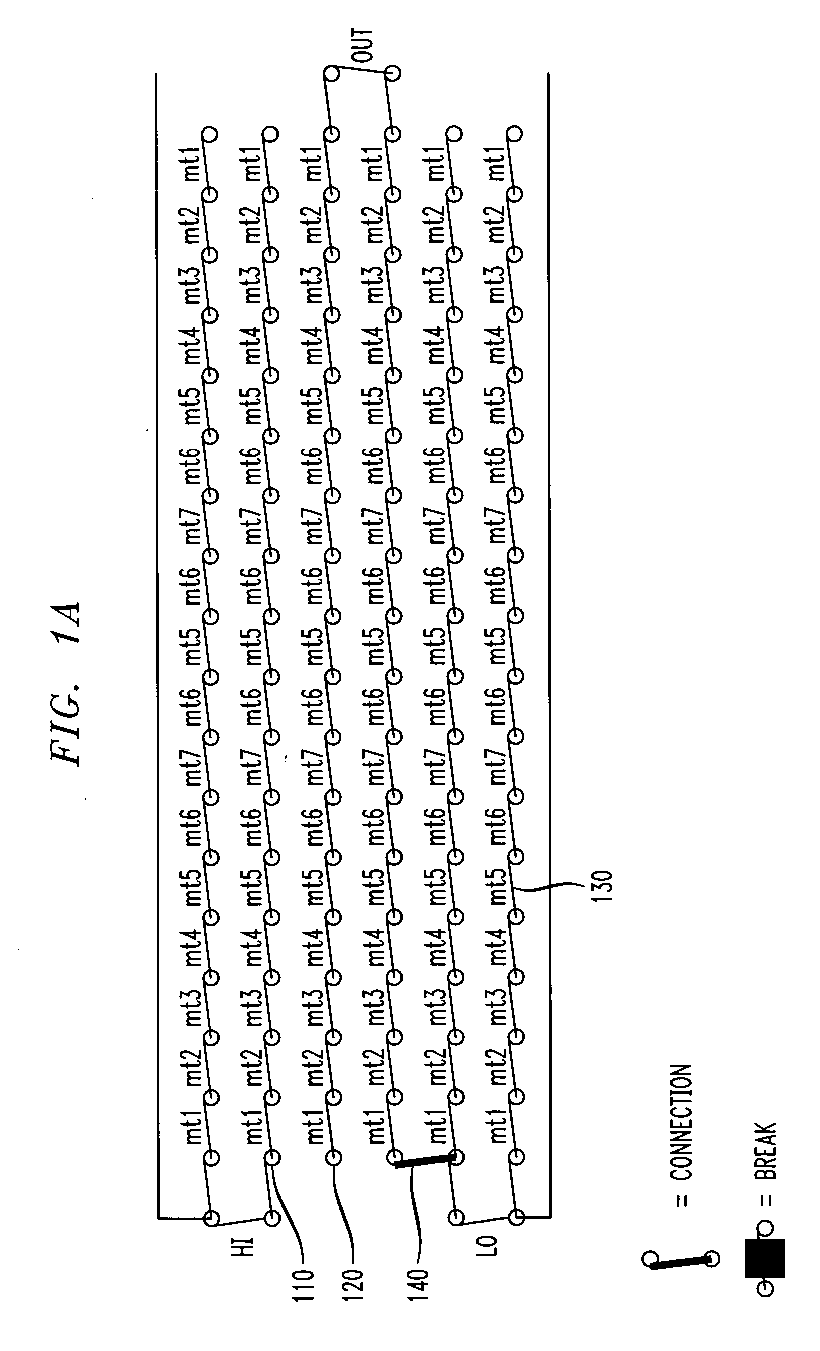
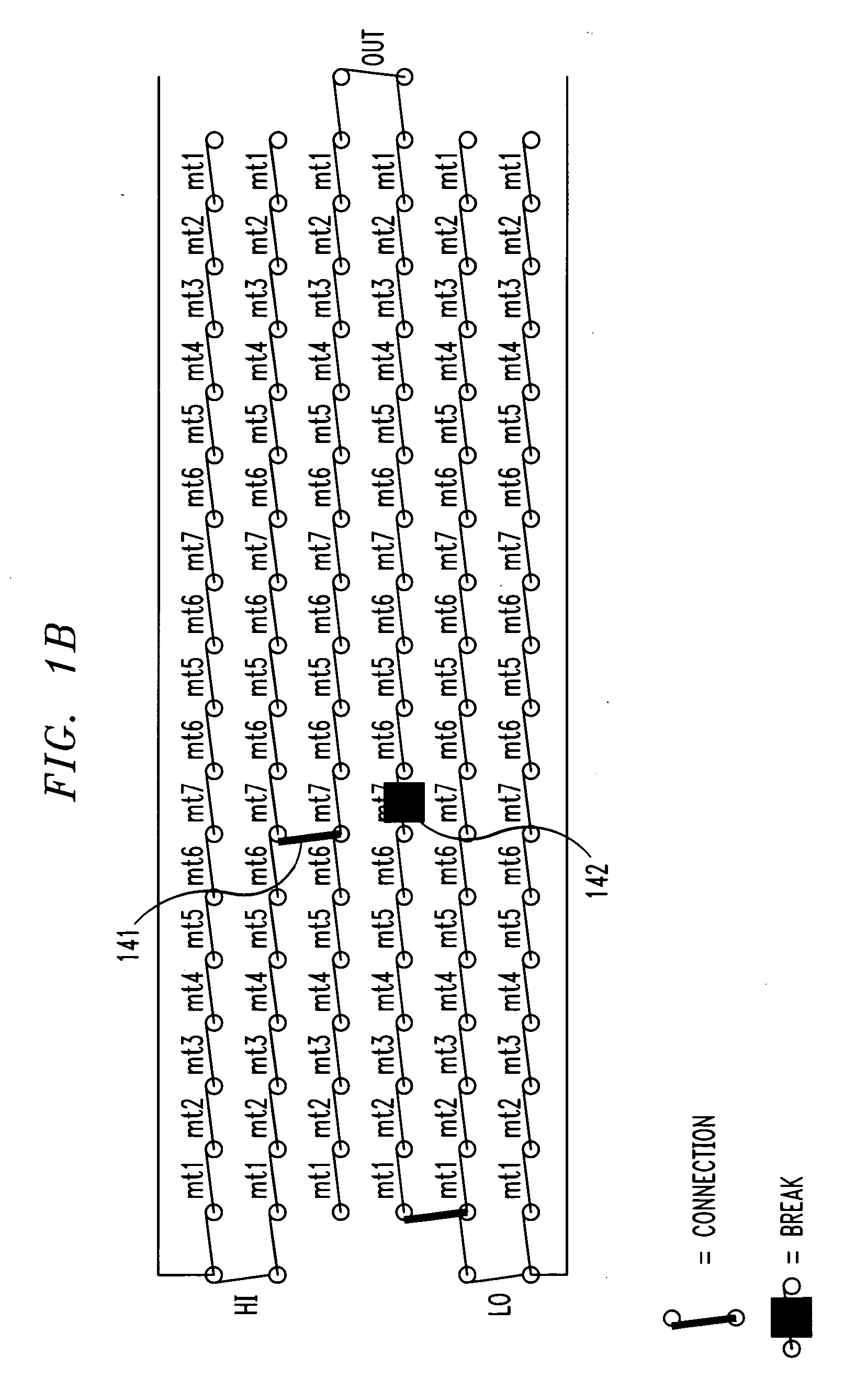
[0008] In an illustrative embodiment, an identification portion of an integrated circuit has an output representing one bit of digital information identifying the integrated circuit. The identification portion is formed of seven metal levels and includes a source of high and low voltage levels. Several metal link features on each of the metal levels connect to lower and higher metal levels through metal vias. The metal links and vias are configured such that the output of the identification can be easily flipped from low to high or high to low by the addition and removal of a metal link from any one of the seven metal levels that form the identification portion. The output can subsequently be flipped a number of more times by adding and removing metal links on any one of the other metal levels or even on a metal level that may have been modified earlier. This illustrative embodiment of a one bit identification portion can, therefore, have its output flipped several times by modifying one metal level each time without any pre-determined order.
[0009] Advantageously, when any one of the metal levels that form the identification portion need to be modified to implement various revisions to the remainder of the integrated circuit, the output of the identification portion can also be changed on the same mask so that the integrated circuit's identification information reflects the revisions. For example, if a single metal layer that forms a part of the identification portion needs to be changed to correct a design error somewhere in the active portion of the integrated circuit, the same metal layer can be concurrently modified to change the identification portion such that its output reflects this design change. The cost of additional masks exclusively for the purpose of updating identification information is thereby avoided.

Problems solved by technology

While such a method may provide identification information while the integrated circuit is being manufactured, such physical identifiers are no longer available after an integrated circuit is encapsulated in an integrated circuit package.
This creates significant added cost.

Method used


Image

  • Techniques for facilitating identification updates in an integrated circuit
  • Techniques for facilitating identification updates in an integrated circuit
  • Techniques for facilitating identification updates in an integrated circuit

Examples


Embodiment Construction

[0015] The present invention will be illustrated below in conjunction with illustrative embodiments of an integrated circuit. It should be understood, however, that the invention is not limited to the particular circuitry arrangements of the illustrative embodiments. An integrated circuit could, for example, contain a different number and arrangement of metal levels from that described by the illustrative embodiments and still fall within the scope of the invention. Other possible modifications to the illustrative embodiments within the scope of this invention will be apparent to those skilled in the art.

[0016] In accordance with one aspect of the invention, an integrated circuit comprises at least two portions. An identification portion has an output that represents one or more bits of digital information identifying the integrated circuit. Furthermore, one or more additional portions of the integrated circuit include active circuitry. The active circuitry may contain digital or a...


PUM


Abstract

An integrated circuit comprises an identification portion having an output representative of one or more bits of digital information identifying the integrated circuit. This identification information may, for example, allow the manufacturer to determine which photolithographic masks were used to manufacture the integrated circuit. The identification portion is formed at least partially by a plurality of metal levels. Modifications to the integrated circuit's identification information are facilitated by designing the identification portion such that its output can be changed by modifying any one metal level among the plurality of metal levels that form it.

Description

FIELD OF THE INVENTION [0001] This invention relates to integrated circuits, and, more specifically, to integrated circuits containing electronically readable identification information. BACKGROUND OF THE INVENTION [0002] Modern integrated circuits commonly include one or more means by which the integrated circuit can be identified. This identification information may, for example, allow the manufacturer to determine which photolithographic masks (“masks”) were used to manufacture the integrated circuit. Masks are frequently changed in order to reduce defects, increase performance or change a circuit design. Embedded identification information allows the manufacturer to readily track such changes. [0003] Many manufacturers indicate mask revisions simply by changing a designator on the masks being revised. The designator is subsequently patterned into the integrated circuit and is available to the manufacturer by optical inspection. While such a method may provide identification info...

Claims


Application Information

Patent Timeline
IPC IPC(8): H01L23/58H01L29/10
CPCH01L23/522H01L2223/5448H01L2223/5444H01L23/544H01L2924/0002H01L2924/00
Inventor BACHMAN, STEVEN C.EDWARDS, LYNN G. JR.
Owner AGERE SYST INC
Learn More