Automatic pushing and positioning device

A positioning device and automatic technology, which is applied in the direction of grinding machines, metal processing equipment, grinding/polishing equipment, etc., can solve the problems of increased processing costs and achieve the effects of high processing costs, avoiding large processing errors and long working hours

Active Publication Date: 2011-09-14
BEIJING NO 2 MACHINE TOOL WORKS
View PDF4 Cites 2 Cited by
  • Summary
  • Abstract
  • Description
  • Claims
  • Application Information

AI Technical Summary

Problems solved by technology

However, in the traditional processing, since it is difficult to use the X surface as the positioning reference during installation, it is converted to the Y surface for positioning. As a result, the actual positioning reference during processing does not coincide with the design reference, and machining errors will inevitably occur. To reduce this error, the usual method is to improve the dimensional accuracy between the X surface and the Y surface, which is not high, which leads to an increase in processing costs.

Method used


Image

  • Automatic pushing and positioning device
  • Automatic pushing and positioning device
  • Automatic pushing and positioning device

Examples


Embodiment Construction

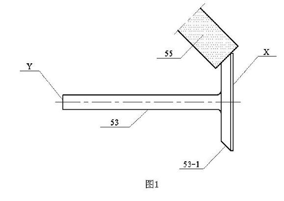
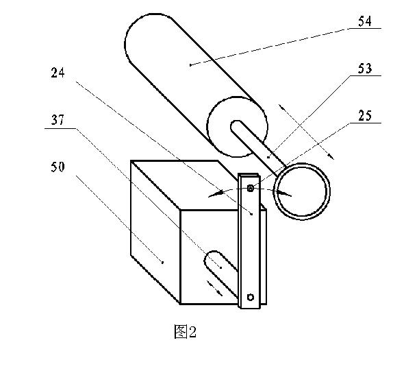
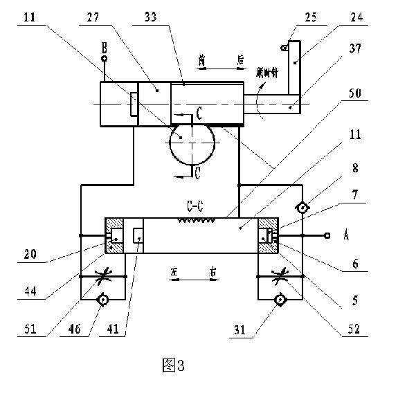
[0028] like Figure 3-5 As shown, the present invention provides an automatic pushing and positioning device, comprising a single-rod hydraulic cylinder and a plunger cylinder, a gear 33 is coaxially arranged between the piston 27 and the piston rod 37 of the single-rod hydraulic cylinder, and the The gear is located in the inner cavity of the cylinder barrel of the single-rod hydraulic cylinder, the piston of the plunger cylinder is a rack plunger 11, and is meshed with the gear, and a swing rod 24 is fixed on the piston rod. The swing rod extends radially of the gear, the swing rod is located outside the cylinder barrel of the single-rod hydraulic cylinder, and the swing rod is provided with a positioning structure 25 for component positioning.

[0029] The gear and the piston or piston rod are integrally structured, or may be rigidly connected or rotatably connected.

[0030] The automatic pushing and positioning device can realize linear reciprocating motion in one direct...


PUM


Abstract

The invention relates to an automatic pushing and positioning device, comprising a single-rod hydraulic cylinder and a plunger cylinder which share one cylinder body, wherein a gear is coaxially arranged between a piston and a piston rod of the single-rod hydraulic cylinder, a piston of the plunger cylinder is a rack plunger, is meshed with the gear and can relatively slide along the extension direction of teeth, a swing rod which extends along the radial direction of the gear is fixed on the piston rod, a positioning structure for positioning parts is arranged on the swing rod, and two hydraulic cylinders controls the motions of the opposite party in certain direction through control oil ports arranged on the lateral wall of respective cylinder. The automatic pushing and positioning device can conveniently realize the coincidence between the practical process reference and the design reference of the workpiece and solves the problems of reference transformation as well as large machining error, high cost and long man-hour caused by reference transformation; in addition, a great amount of control valves and indication switches can be saved by adopting a hydraulic element structure integrating the functions of the hydraulic cylinder and the control valve into a whole, and reliable interlocking of motion time can be ensured.

Description

technical field [0001] The invention relates to an automatic tooling device for pushing and positioning workpieces during mechanical processing, in particular to an automatic device for automatically pushing and positioning internal combustion engine valves. Background technique [0002] like figure 1 As shown, when grinding the conical surface 53-1 of the workpiece 53 (internal combustion engine valve), the design basis of the axial dimension of the conical surface is the X plane, so ideally, when the internal combustion engine valve is installed on the machine tool, it must be ensured that The specific distance between the X surface and the grinding wheel 55 can ensure the stability of workpiece size during batch grinding. However, in the traditional processing, since it is difficult to use the X surface as the positioning reference during installation, it is converted to the Y surface for positioning. As a result, the actual positioning reference during processing does n...

Claims


Application Information

Patent Timeline
Patent Type & Authority Applications(China)
IPC IPC(8): B24B19/09
Inventor 刘德鉁薛建林穆东辉李伟华张秀兰傅伟男
Owner BEIJING NO 2 MACHINE TOOL WORKS
Why Eureka
Try Eureka