
RFID tags having improved read range

Inactive Publication Date: 2006-10-05
EMERSON & CUMING MICROWAVE PRODS
View PDF5 Cites 33 Cited by
  • Summary
  • Abstract
  • Description
  • Claims
  • Application Information

AI Technical Summary

Benefits of technology

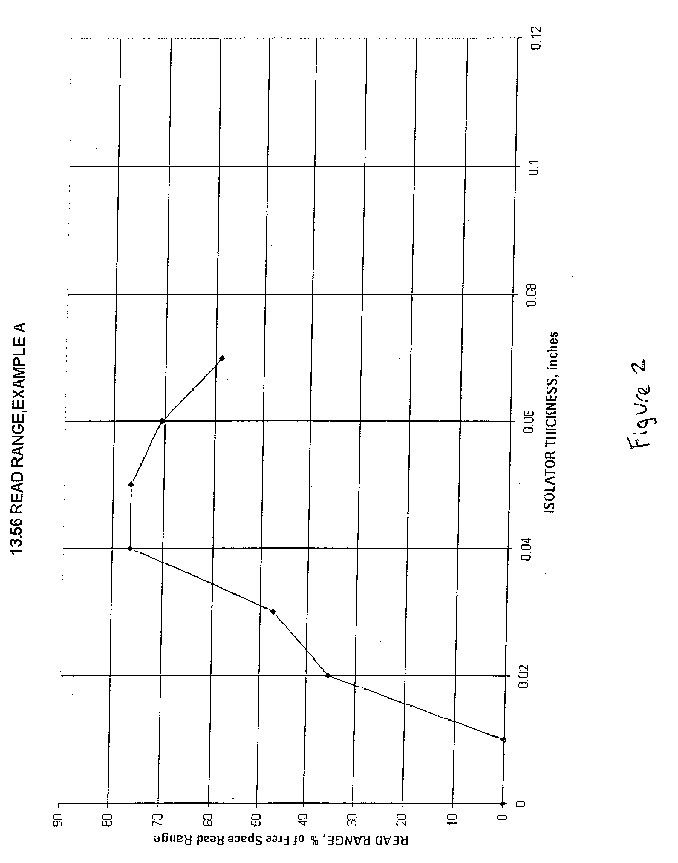
[0012] The present invention provides a system for effectively isolating a substrate from an RFID tag and a method for optimizing the performance of 13.56 MHz frequency RFID tags in conjunction with metal substrates. Briefly, a thickness exists for each type of RFID isolator material at which the performance o

Problems solved by technology

Varying from this optimal value, in either the positive or negative direction adversely affects read distance.

Method used


Image

  • RFID tags having improved read range
  • RFID tags having improved read range
  • RFID tags having improved read range

Examples


Embodiment Construction

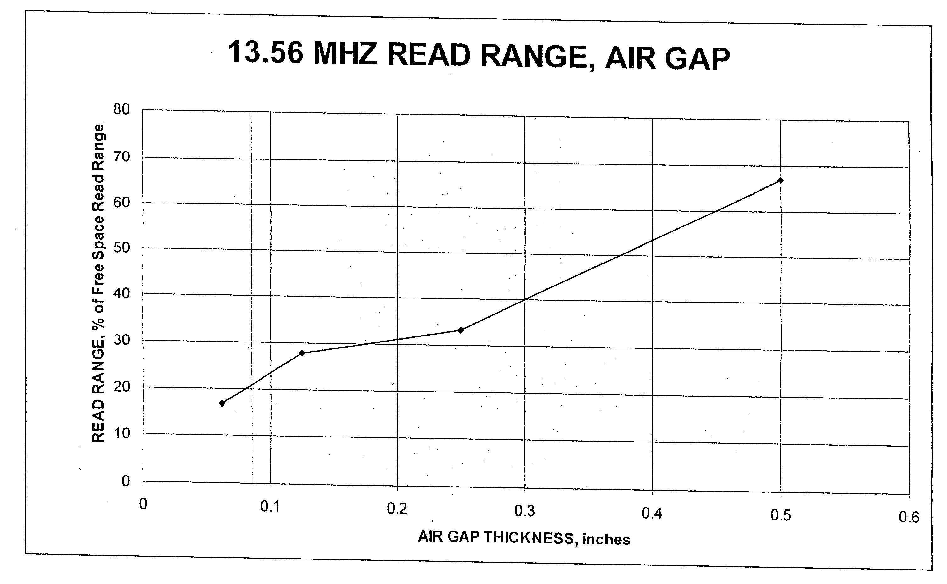
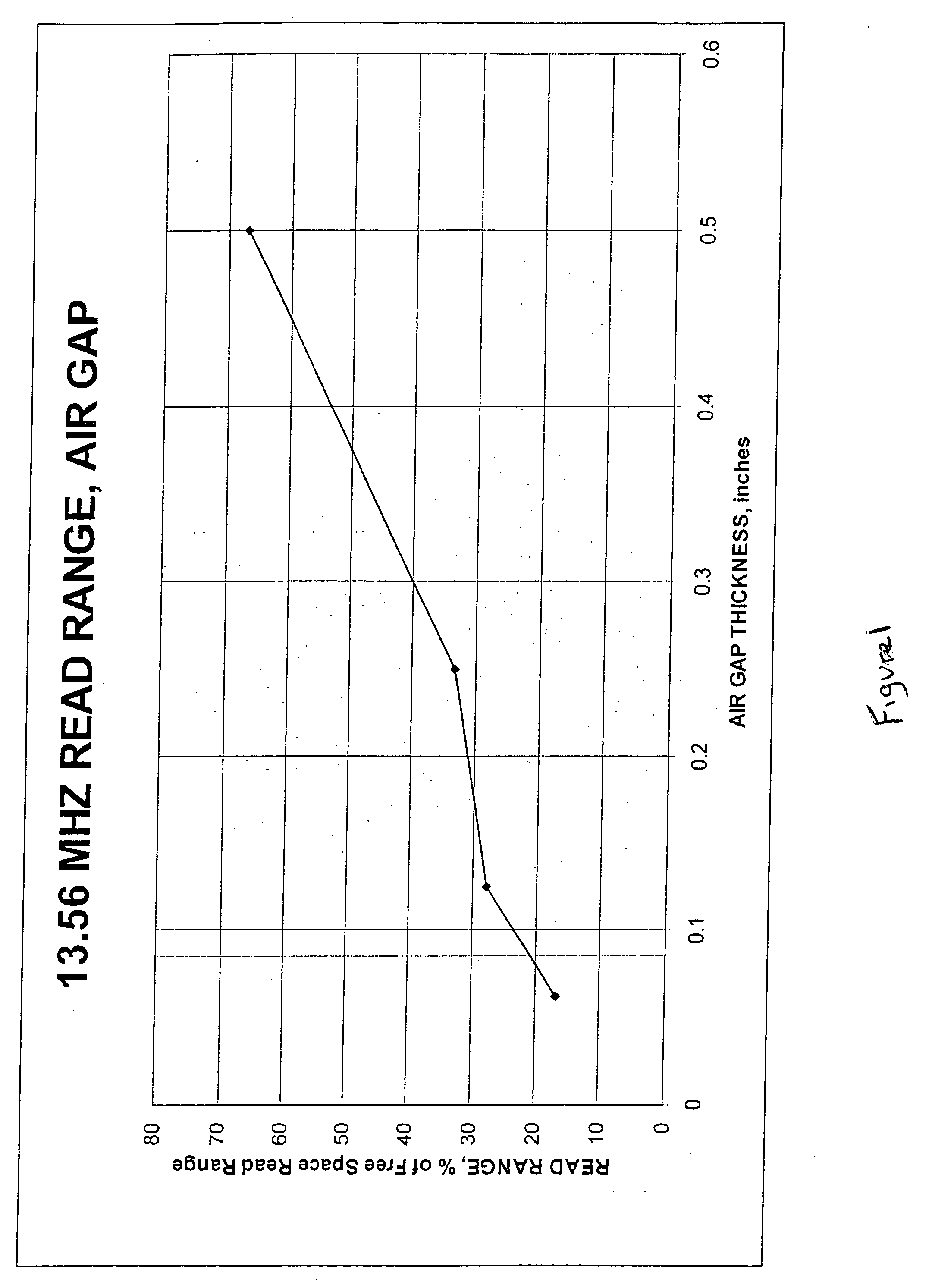
[0024] As described above, an air gap between an RFID tag and a metal surface is traditionally used to improve the read distance of the tag. Larger air gaps (i.e. taller standoffs) are superior to narrower gaps. Because of the degradation of the read distance at close proximity to the metal substrate, standoffs are typically more than 0.25 inches thick. Based on FIG. 1, this represents a read distance of approximately 33% of the free space read distance. Increasing the standoff to 0.5 inches doubles the read distance of the RFID tag. However, a standoff of this height is susceptible to being damaged or being separated from the article. Thus, the designer is faced with a tradeoff between maximizing read distance by increasing the height of the standoff, and minimizing the susceptibility of the RFID tag to damage by reducing the height of the standoff.

[0025] Alternatively, the RFID Handbook suggests the use of highly permeable ferrite between the antenna coil and the metal substrate ...


PUM

PropertyMeasurementUnit
Thicknessaaaaaaaaaa
Frequencyaaaaaaaaaa
Thicknessaaaaaaaaaa

Abstract

The present invention provides a system and method for optimizing the performance of 13.56 MHz frequency RFID tags in conjunction with metal substrates. Briefly, a thickness exists for each type of RFID isolator material at which the performance of a 13.56 MHz RFID tag is optimal when used with metal. Varying from this optimal value, in either the positive or negative direction adversely affects read distance. A method of determining this optimal thickness is disclosed, as well as an RFID tag or a substrate being used in conjunction with a material of this thickness.

Description

[0001] This application claims priority of U.S. Provisional Application Ser. No. 60 / 665,990, filed Mar. 29, 2005, the disclosure of which is incorporated herein by reference.BACKGROUND OF THE INVENTION [0002] Radio Frequency Identifier (RFID) tags are used in a variety of applications, such as inventory control and security. The advantage of these more intelligent RFID systems is that, unlike barcode tracking systems, an RFID system can store specific information about an article and can read that information on a tag without requiring line of sight or a particular orientation. This means that RFID systems can be largely automated, reducing the need for manual scanning. [0003] These RFID tags are typically placed on or in articles or containers such as cardboard boxes. The RFID tags work in conjunction with an RFID base station. The base station supplies an electromagnetic wave output, which acts as the carrier frequency. Data are then used to modulate the carrier frequency to trans...

Claims


Application Information

Patent Timeline
IPC IPC(8): G08B13/14
CPCG06K19/07749Y10T428/12493G06K19/07771
Inventor DIXON, PAUL F.CARPENTER, MICHAEL P.OSWARD, MARY M.GIBBS, DAVID A.
Owner EMERSON & CUMING MICROWAVE PRODS
Learn More