Liquid ejection head and liquid ejection apparatus

Inactive Publication Date: 2006-10-05
FUJIFILM CORP
View PDF2 Cites 15 Cited by
  • Summary
  • Abstract
  • Description
  • Claims
  • Application Information

AI Technical Summary

Benefits of technology

[0044] According to this aspect, it is possible to suppress the effects of cross-talk.
[0045] As described above, according to the liquid ejection head relating to the present invention, it is possible to achieve a high-density arrangement of the electrical wires which carry determination signals from the pressure sensors.
[0046] Furthermore, according to the liquid ejection apparatus relating to the present invention, it is possible to achieve even higher density of the electrical wires from the electrodes which cause

Problems solved by technology

Hence, it may become difficult to eject ink droplets satisfactorily, and nozzle blockages leading to ejection failures may occur.
Furthermore, interruption of the ink supply may occur if there is stagnation of air bubbles introduced into the ink supply channels, or the like, and the delay of ink refilling leading to ejection defects may occur if an ejection operation is continued for a long period of time.
If maintenance is carried out frequently, then the recording efficiency declines.
If the pressure chambers and t

Method used


Image

  • Liquid ejection head and liquid ejection apparatus
  • Liquid ejection head and liquid ejection apparatus
  • Liquid ejection head and liquid ejection apparatus

Examples


first embodiment

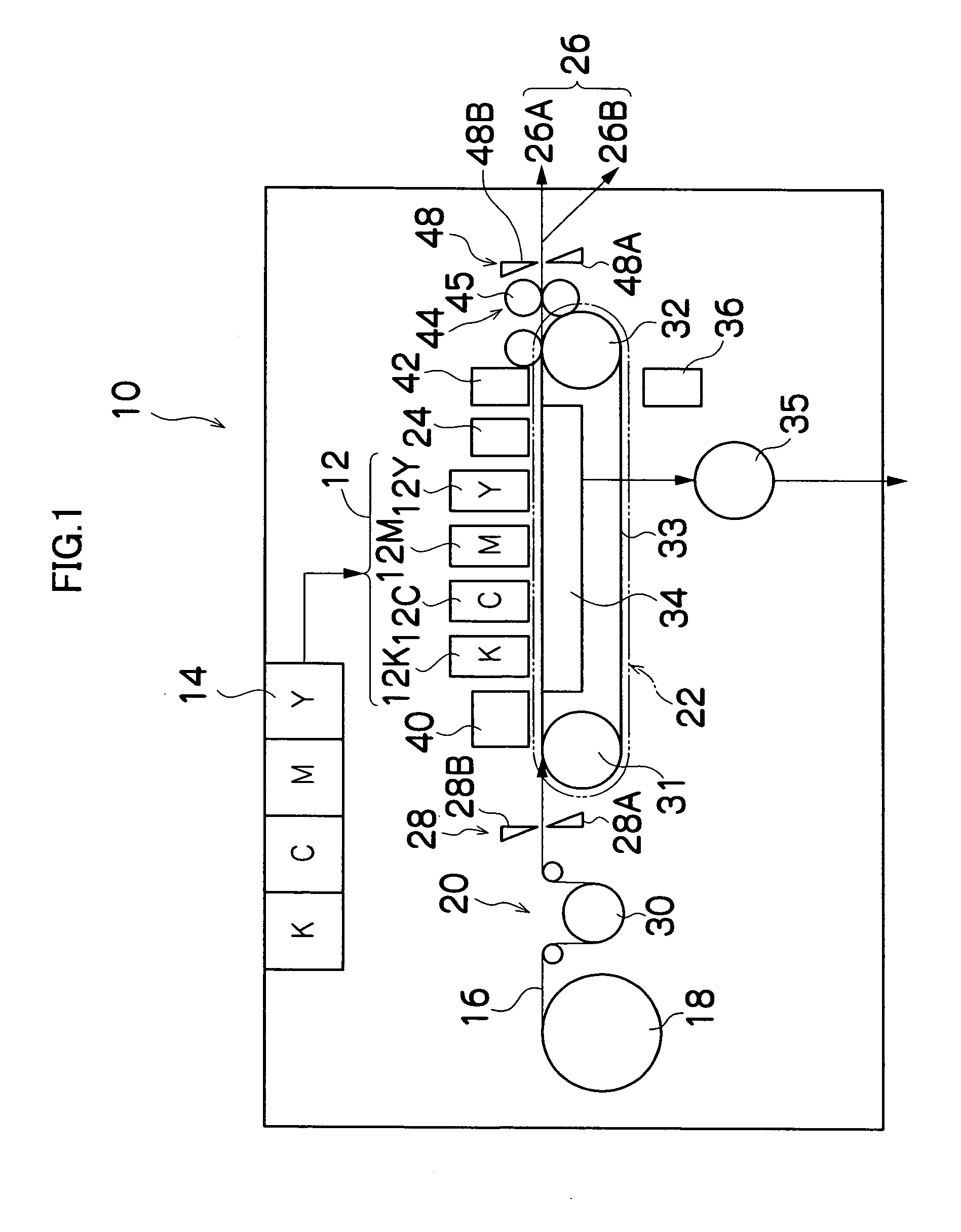
[0068]FIG. 1 is a general schematic drawing showing an approximate view of an inkjet recording apparatus forming an image forming apparatus comprising a liquid ejection apparatus having a liquid ejection head relating to the present invention.

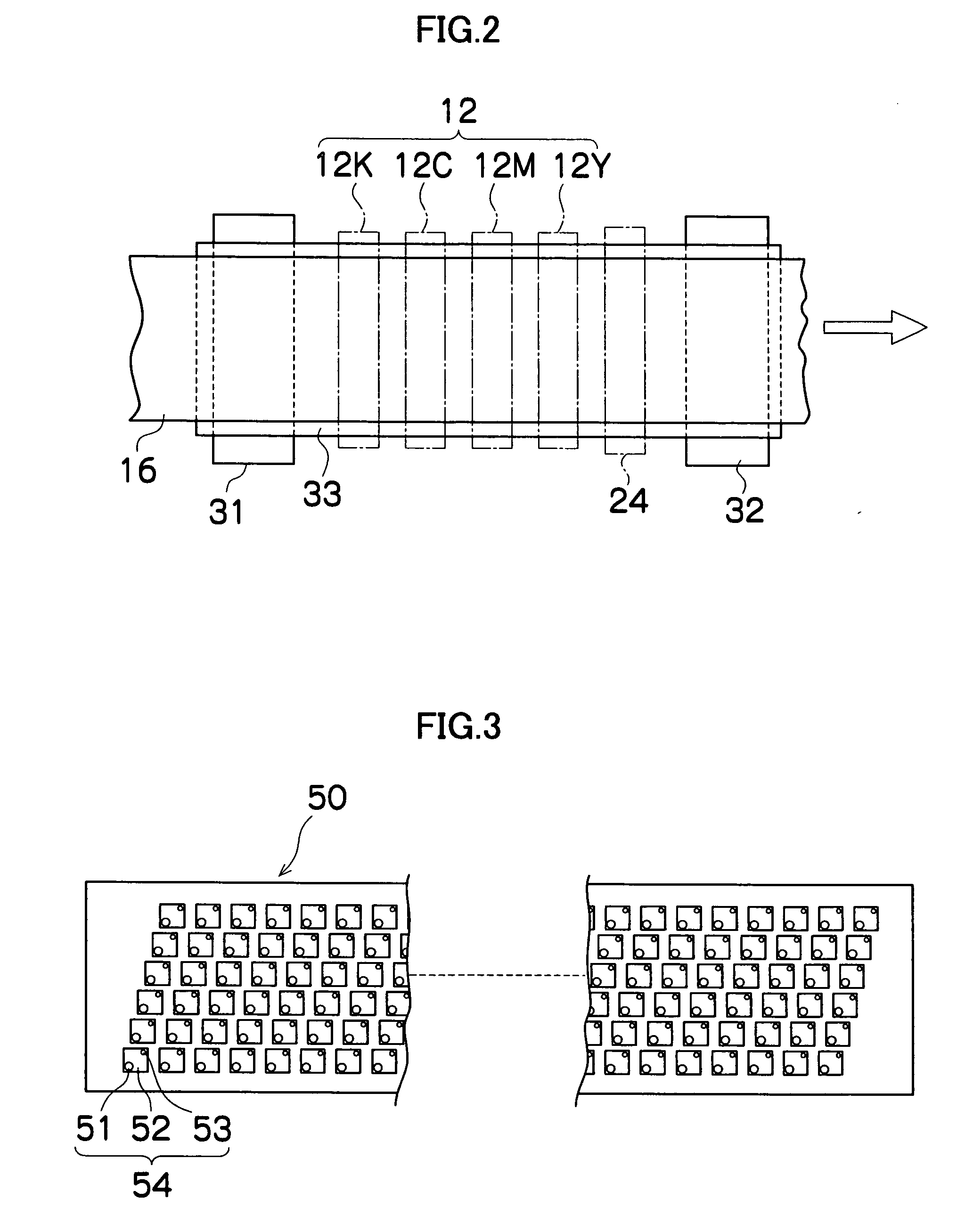
[0069] As shown in FIG. 1, the inkjet recording apparatus 10 comprises: a printing unit 12 having a plurality of print heads (liquid ejection heads) 12K, 12C, 12M, and 12Y for ink colors of black (K), cyan (C), magenta (M), and yellow (Y), respectively; an ink storing and loading unit 14 for storing inks of K, C, M and Y to be supplied to the print heads 12K, 12C, 12M, and 12Y; a paper supply unit 18 for supplying recording paper 16; a decurling unit 20 for removing curl in the recording paper 16; a suction belt conveyance unit 22 disposed facing the nozzle face (ink-droplet ejection face) of the print unit 12, for conveying the recording paper 16 while keeping the recording paper 16 flat; a print determination unit 24 for reading the printed r...

second embodiment

[0200] Next, the present invention is described.

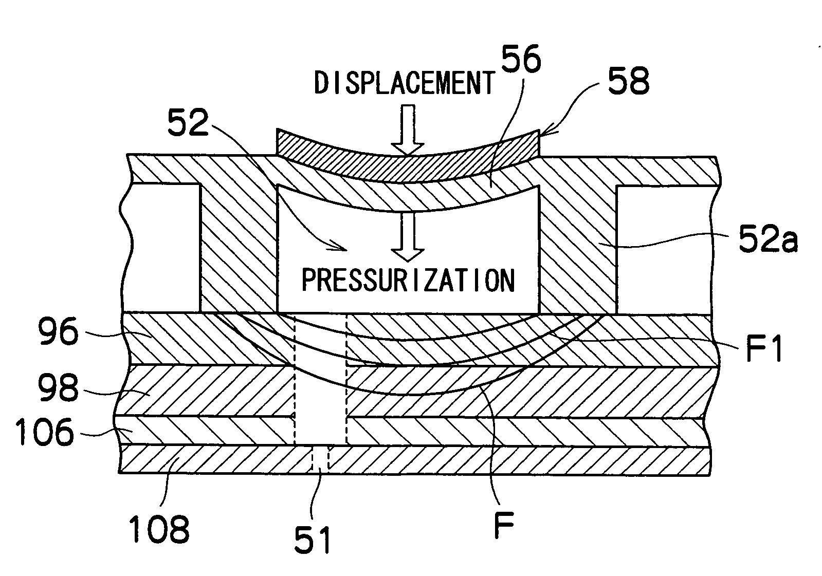
[0201] The second embodiment is devised in order to suppress cross-talk which may occur when the pressure chambers, pressure sensors and electrical wires extended from the pressure sensors are arranged at high density as in the first embodiment described above.

[0202] The general composition of the inkjet recording apparatus comprising the liquid ejection apparatus according to the present embodiment is basically the same as the first embodiment shown in FIGS. 1 to 5. The parts of the composition of this apparatus which are different from those in the first embodiment are described below, and constituent elements which are the same as the first embodiment are labeled with the same reference numerals and detailed description thereof is omitted here.

[0203]FIG. 18 shows a block diagram of the main parts of the system composition of the inkjet recording apparatus 110 relating to the second embodiment.

[0204] As shown in FIG. 18, the inkje...


PUM


Abstract

The liquid ejection head has nozzles for ejecting liquid in which a plurality of pressure chambers are arranged in a two-dimensional matrix configuration. The liquid ejection head comprises: pressure generating devices which are disposed so as to correspond to the pressure chambers and generate pressure for ejecting the liquid in the pressure chambers; pressure sensor members formed in at least two layers which determine the pressure inside the pressure chambers generated by the pressure generating devices; and electrodes which are disposed on both surfaces of one of the layers of the pressure sensor members and cause the one of the pressure sensor members to become effective determination sections.

Description

BACKGROUND OF THE INVENTION [0001] 1. Field of the Invention [0002] The present invention relates to a liquid ejection head and liquid ejection apparatus, and more particularly, to a liquid ejection head and liquid ejection apparatus comprising a pressure sensor which determines an ejection defect by determining the ink pressure inside a pressure chamber. [0003] 2. Description of the Related Art [0004] As an image forming apparatus, an inkjet recording apparatus (inkjet printer) has been known, which comprises an inkjet head (liquid ejection head) having an arrangement of a plurality of nozzles (liquid ejection ports) and forms images on a recording medium by ejecting ink (ink droplets) from the nozzles toward the recording medium while the inkjet head and the recording medium are caused to move relatively to each other. [0005] Various methods are known as the ink ejection methods for an inkjet recording apparatus of this kind. For example, a piezoelectric method is known, in which ...

Claims


Application Information

Patent Timeline
IPC IPC(8): B41J2/045
CPCB41J2/14233B41J2/145B41J2002/14354B41J2202/20B41J2002/14491B41J2202/11B41J2002/14459
Inventor NAGASHIMA, KANJI
Owner FUJIFILM CORP
Why Eureka
Try Eureka