X-ray generator and adjustment method therefor

Inactive Publication Date: 2017-01-05
RIGAKU CORP
View PDF2 Cites 4 Cited by
  • Summary
  • Abstract
  • Description
  • Claims
  • Application Information

AI Technical Summary

Benefits of technology

[0013]According to the present invention, the X-ray generator capable of suppressing effects of

Problems solved by technology

However, all the above-mentioned methods have problems in that costs are significantly high and the degree of freedom is extremely limited for a location of installation of the electron-beam applied apparatus and displacement of the electron-beam

Method used


Image

  • X-ray generator and adjustment method therefor
  • X-ray generator and adjustment method therefor
  • X-ray generator and adjustment method therefor

Examples


Embodiment Construction

[0018]Now, an embodiment of the present invention is described referring to the drawings. For clearer illustration, some sizes, shapes, and the like are schematically illustrated in the drawings in comparison to actual ones. However, the sizes, the shapes, and the like are merely an example, and do not limit understanding of the present invention. Further, like elements as those described relating to the drawings already referred to are denoted by like reference symbols herein and in each of the drawings, and detailed description thereof is sometimes omitted as appropriate.

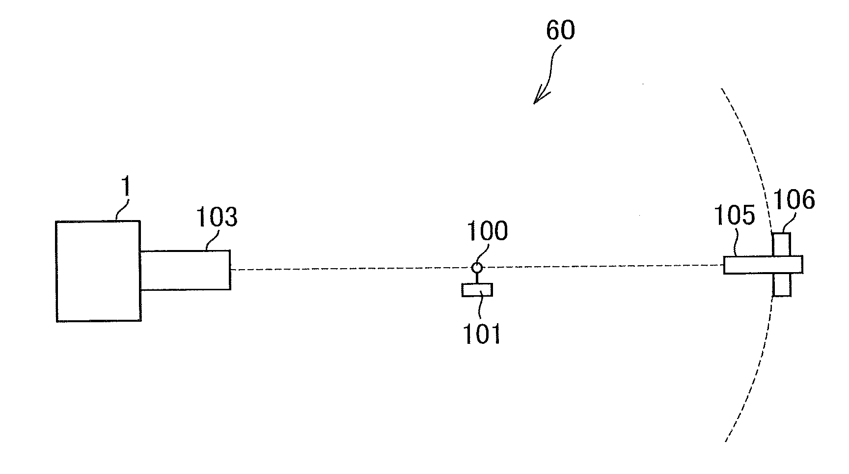
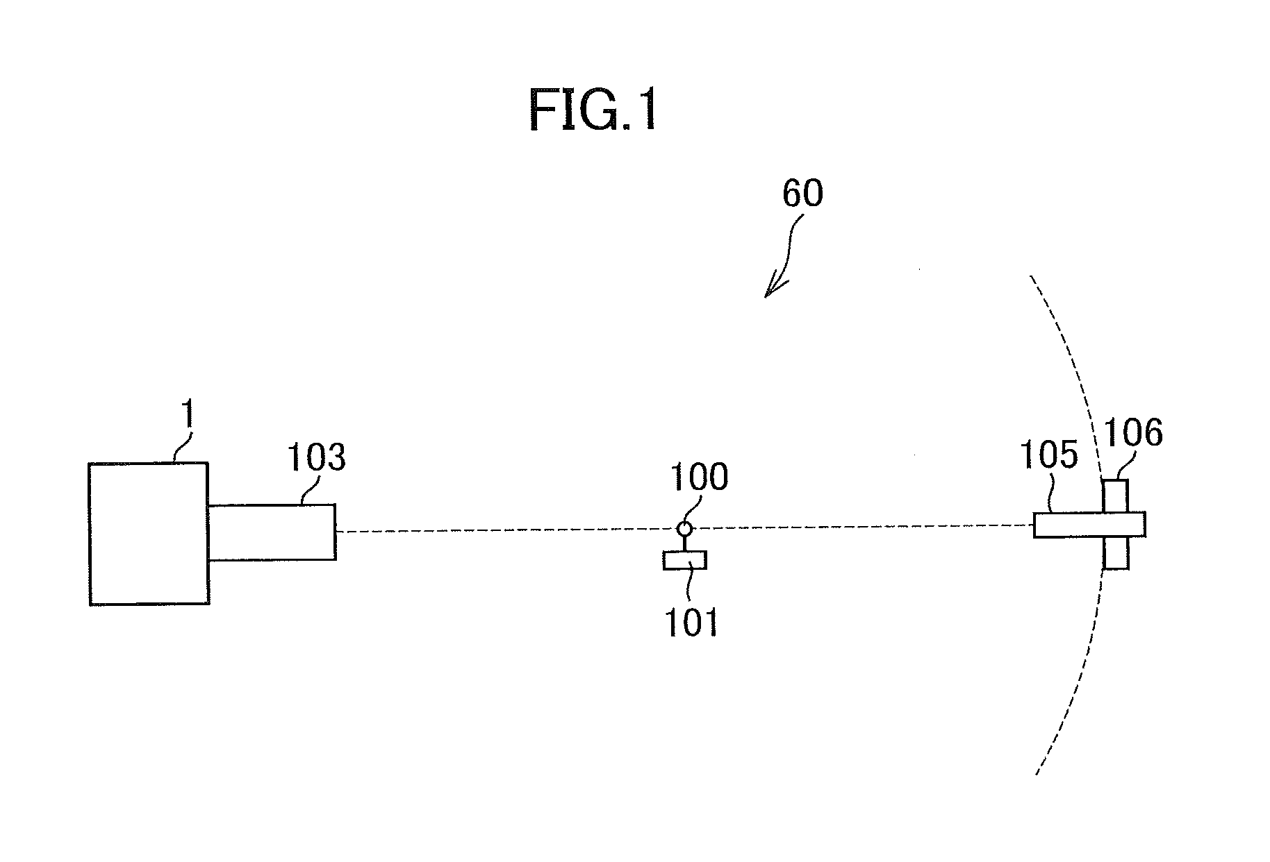
[0019]FIG. 1 is a schematic diagram for illustrating the structure of an X-ray analyzer 60 according to an embodiment of the present invention. The X-ray analyzer 60 according to this embodiment is, for example, an X-ray diffraction (XRD) system. The X-ray analyzer 60 includes an X-ray generator 1, a sample stage 101, an optical system 103, an X-ray detector 105, and a rotary drive system 106.

[0020]A main feature ...


PUM


Abstract

Provided are an X-ray generator capable of suppressing effects of a fluctuation in a disturbance magnetic field and an adjustment method therefor. The X-ray generator includes: an electron-beam generating unit configured to emit an electron beam; an electron target onto which the electron beam is radiated to generate an X-ray; an electron-beam adjusting unit, which is arranged between the electron-beam generating unit and the electron target, and is configured to adjust the electron beam emitted from the electron-beam generating unit; an electron-beam deflecting unit, which is arranged between the electron-beam adjusting unit and the electron target, and is configured to deflect the electron beam to be radiated onto the electron target; and a magnetic sensor arranged in a vicinity of a region of the electron target, onto which the electron beam is radiated, so as to be away from the electron beam.

Description

CROSS-REFERENCE TO RELATED APPLICATION[0001]The present application claims priority from Japanese application JP 2015-132907, filed on Jul. 1, 2015, the content of which is hereby incorporated by reference into this application.BACKGROUND OF THE INVENTION[0002]1. Field of the Invention[0003]The present invention relates to an X-ray generator and an adjustment method therefor, and more particularly, to a technology for suppressing the effects of a fluctuation in a disturbance magnetic field.[0004]2. Description of the Related Art[0005]Apparatus using an electron beam (hereinafter referred to as “electron-beam applied apparatus”) include an electron microscope, an electron-beam lithography system, and an X-ray generator. The electron beam is an electron swarm that travels at high speed, in which each electron has a charge. Therefore, the electrons that travel through a magnetic field experience a Lorentz force to change a traveling direction thereof. Thus, the electron-beam applied ap...

Claims


Application Information

Patent Timeline
IPC IPC(8): H01J35/14
CPCH01J37/09H01J35/147H01J35/153
Inventor NONOGUCHI, MASAHIRO
Owner RIGAKU CORP
Why Eureka
Try Eureka