Semiconductor device and method of manufacturing the same

Inactive Publication Date: 2005-04-28
NEC ELECTRONIS CORP
View PDF7 Cites 2 Cited by
  • Summary
  • Abstract
  • Description
  • Claims
  • Application Information

AI Technical Summary

Benefits of technology

[0018] This method allows manufacturing a semiconductor device capable of outputting a stable and constant voltage or current from a circuit having the first semiconductor element (for example, a reference voltage generator circuit or a constant current circuit) since the impurity concentration of the channel region of the first semiconductor element is uniform, and capa

Problems solved by technology

Further, since the impurity concentration of the channel region of the second circuit i

Method used


Image

  • Semiconductor device and method of manufacturing the same
  • Semiconductor device and method of manufacturing the same
  • Semiconductor device and method of manufacturing the same

Examples


Embodiment Construction

[0028] The invention will be now described herein with reference to illustrative embodiments. Those skilled in the art will recognize that many alternative embodiments can be accomplished using the teachings of the present invention and that the invention is not limited to the embodiments illustrated for explanatory purposed.

[0029] A semiconductor device and a method of manufacturing the same according to one embodiment of the invention are explained hereinafter with reference to FIGS. 1 to 7.

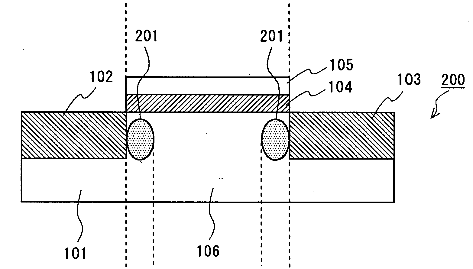
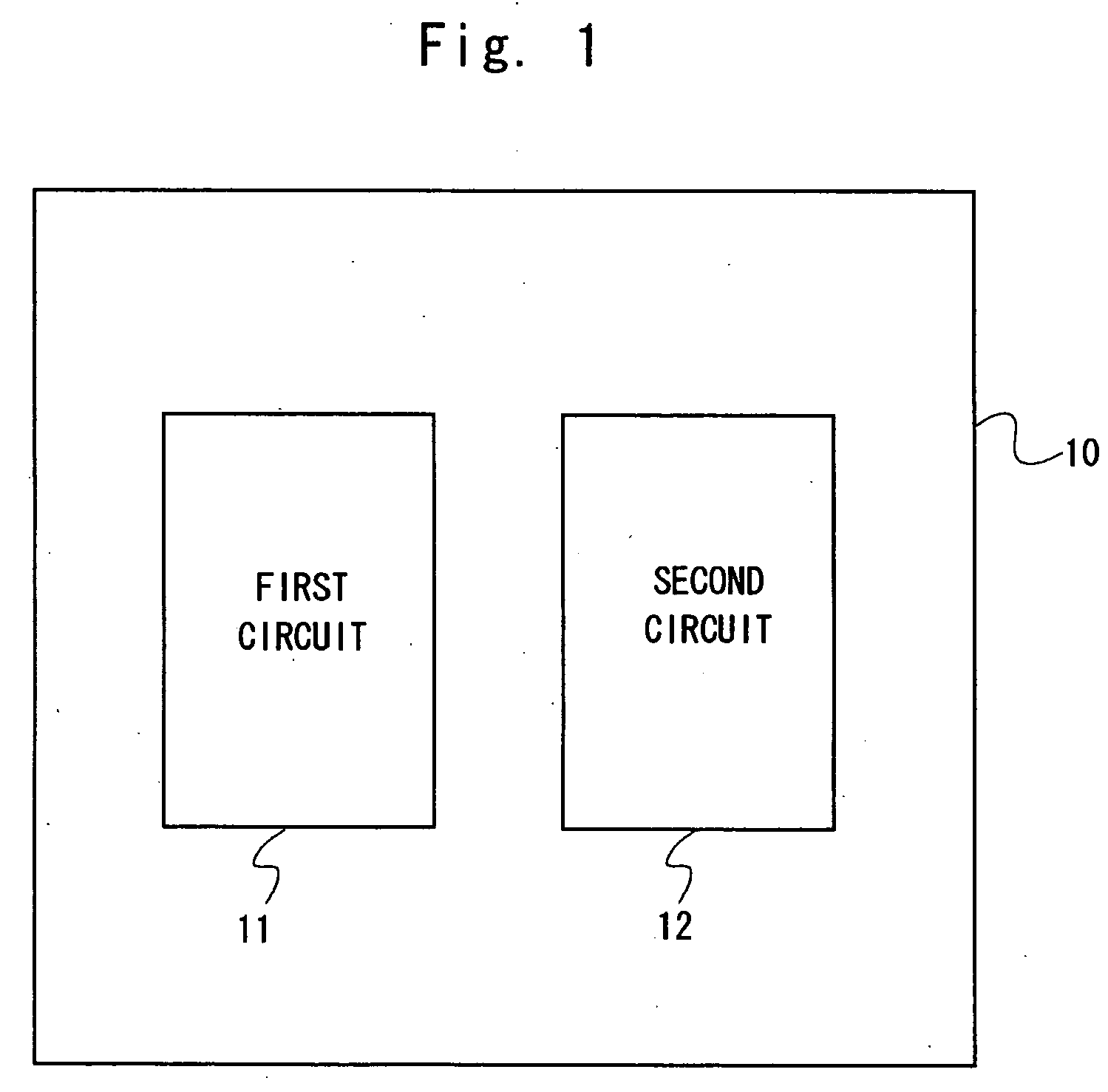
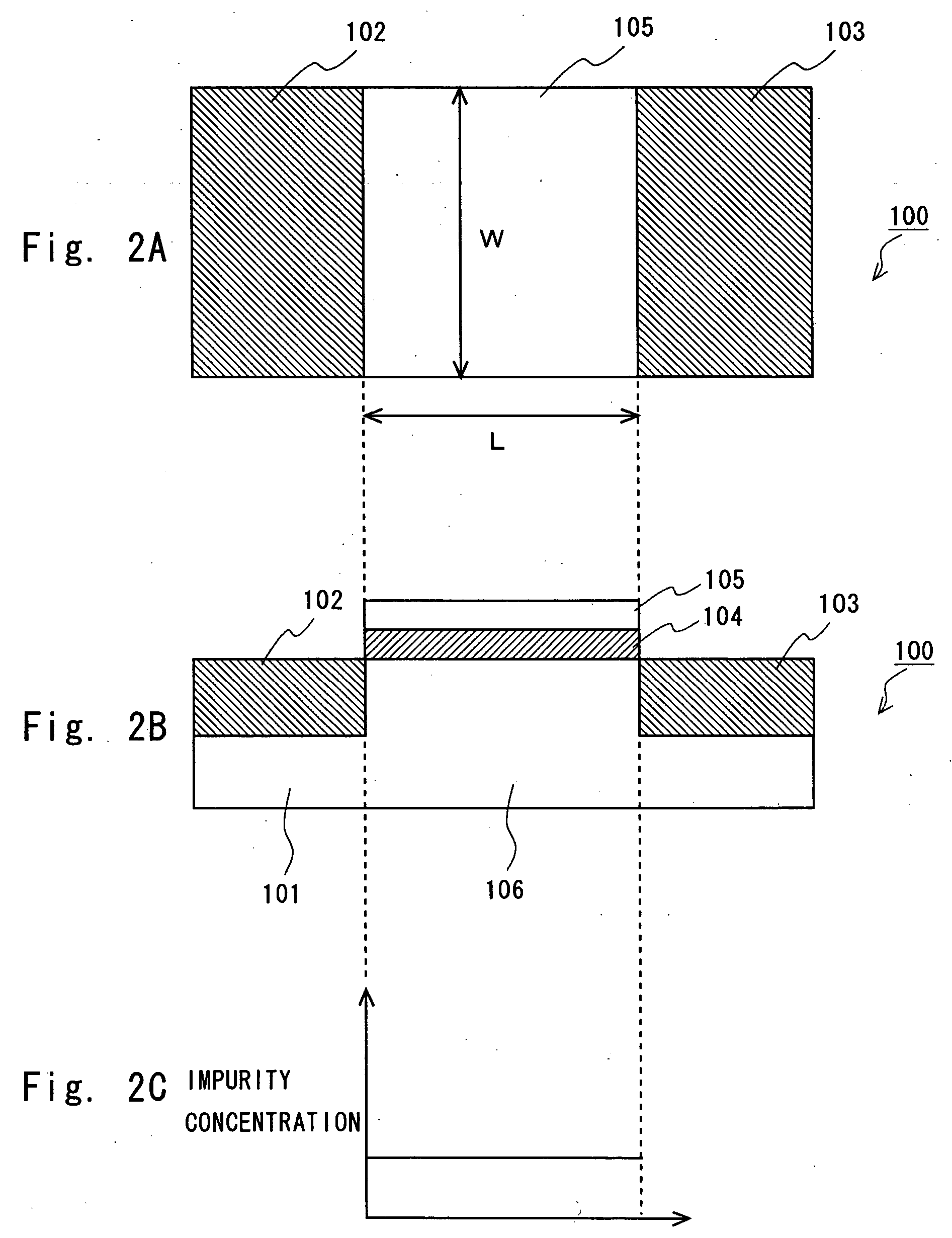
[0030]FIG. 1 is a top view of a semiconductor device of this embodiment. FIGS. 2A to 2C and FIGS. 3A to 3C are block diagrams of a semiconductor element used in the semiconductor device of this embodiment. FIG. 4 is a circuit diagram of a reference voltage generator circuit of this embodiment. FIG. 5 is a flowchart showing a method of manufacturing a semiconductor device of this embodiment. FIG. 6 is a graph showing an input voltage and output voltage regulation in the reference voltage gener...


PUM


Abstract

The semiconductor device includes a reference voltage generator circuit and a circuit different from the reference voltage generator circuit. A semiconductor element of the reference voltage generator circuit has a channel region where a substrate impurity concentration is substantially uniform at least in the vicinity of a drain region. A semiconductor element of the circuit different from the reference voltage generator circuit has a channel region where a substrate impurity concentration is higher than in other part of the region at least in the drain region.

Description

BACKGROUND OF THE INVENTION [0001] 1. Field of the Invention [0002] The present invention relates to a semiconductor device and a method of manufacturing the same. [0003] 2. Description of Related Art [0004] Higher density and higher speed are required for semiconductor integrated circuit devices, which are referred to hereinafter simply as the semiconductor devices, to improve performance. To meet these requirements, miniaturization of component devices is necessary. Thus, microfabrication technology has been developed and various structures and manufacturing methods for achieving high-speed operation of devices have been studied. [0005] Metal Oxide Semiconductor Field Effect Transistors (MOSFET or MOS transistor) are miniaturized usually by reducing a gate length. As the miniaturization of the MOSFET proceeds, however, the effect of a drain electric field on an electric field of a channel region becomes unignorable. This causes a short-channel effect, which is abrupt change in a t...

Claims


Application Information

Patent Timeline
IPC IPC(8): H01L27/04H01L21/822H01L21/8234H01L27/088H01L27/148H01L29/10H01L29/78
CPCH01L21/823412H01L29/1045H01L27/088
Inventor KATSUKI, NOBUYUKIOGA, ATSUSHISENOU, SHUUICHIOTA, NORIYUKIYOSHIDA, MASAHIROARAI, KENTANAKAGAWA, ATSUSHIMURAKAMI, TOMOTAKA
Owner NEC ELECTRONIS CORP
Why Eureka
Try Eureka