
Fly's eye condenser and illumination system therewith

Inactive Publication Date: 2006-10-05
CARL ZEISS SMT GMBH
View PDF9 Cites 62 Cited by
  • Summary
  • Abstract
  • Description
  • Claims
  • Application Information

AI Technical Summary

Benefits of technology

The invention provides a fly's eye condenser for an illumination system of a microlithography projection exposure installation. The condenser has a raster arrangement of optical groups for producing a large number of optical channels. It also has polarization-changing means in at least some of the optical groups for influencing the polarization state of the light passing through the channels. The fly's eye condenser has both homogenizing and polarization-changing properties, and can be manufactured with polarization-changing means adapted for each optical channel. The technical effects of the invention include improved homogenization and control over the polarization state of the light.

Problems solved by technology

In this case, the problem arises of illuminating this illumination surface as homogeneously as possible with the light from the light source.

Method used


Image

  • Fly's eye condenser and illumination system therewith
  • Fly's eye condenser and illumination system therewith
  • Fly's eye condenser and illumination system therewith

Examples


Embodiment Construction

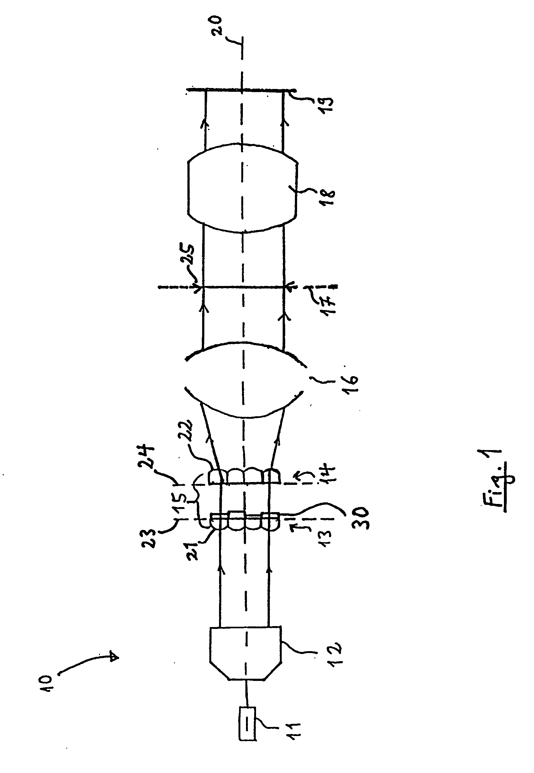
[0056]FIG. 1 shows an embodiment of an illumination system 10 of a microlithography projection exposure system, which can be used during the production of semiconductor components and other finely structured components and, in order to achieve resolutions down to fractions of micrometres, operates with light from the deep ultraviolet range. The primary light source 11 used is an F2 excimer laser having an operating wavelength of about 157 nm, whose light beam is aligned coaxially with respect to the optical axis 20 of the illumination system. Other UV light sources, for example ArF excimer lasers with 193 nm operating wavelength, KrF excimer lasers with 248 nm operating wavelength and primary light sources with higher or lower operating wavelengths are likewise possible.

[0057] The light beam coming from the laser with a small rectangular cross section firstly strikes beam-expanding optics 12, which produce an emergent beam with largely parallel light and a larger rectangular cross ...


PUM

PropertyMeasurementUnit
thicknessaaaaaaaaaa
thicknessaaaaaaaaaa
thicknessesaaaaaaaaaa

Abstract

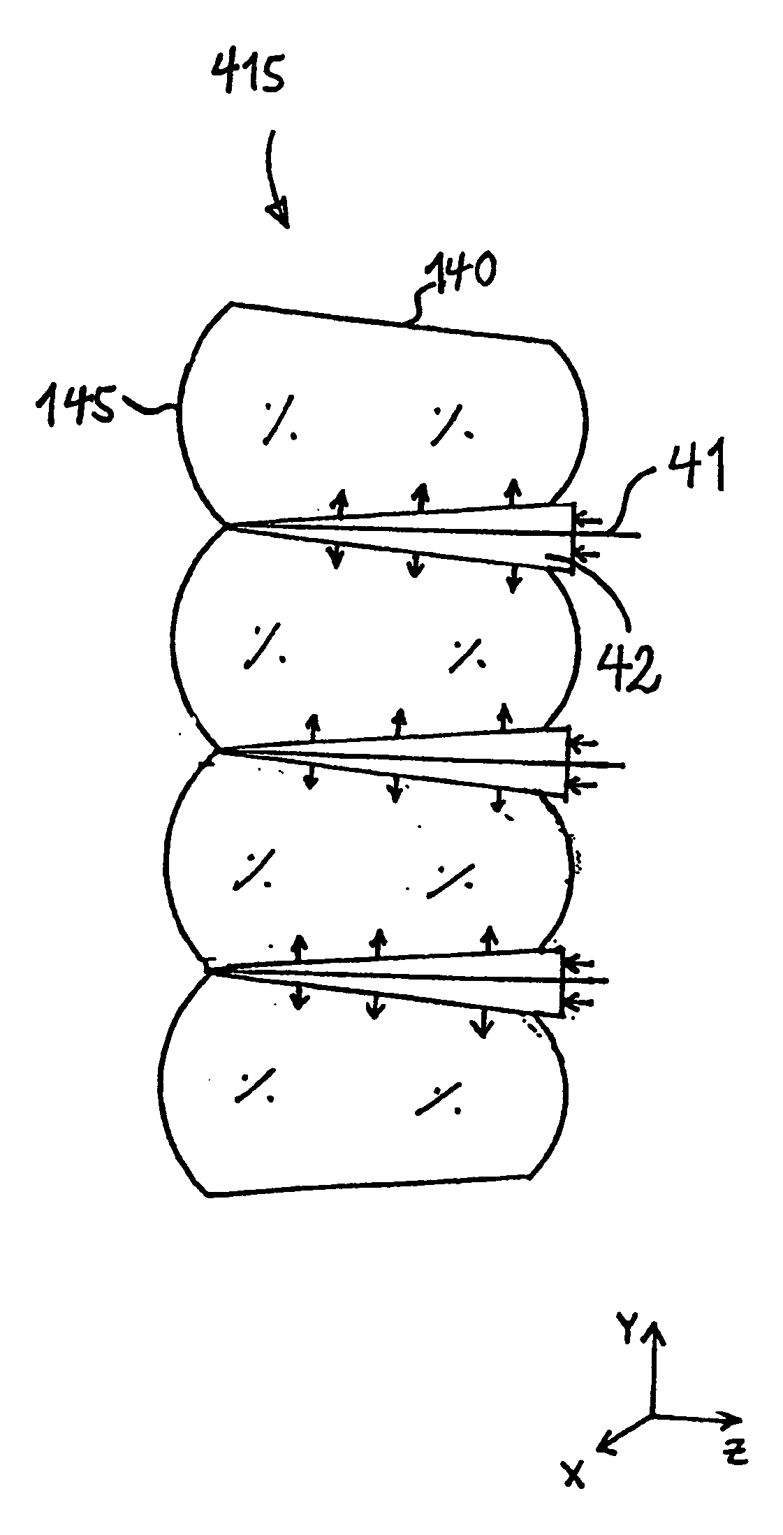
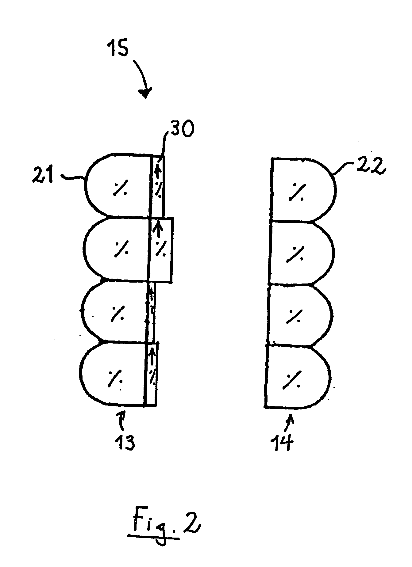
A fly's eye condenser (15) for converting an input light distribution into an output light distribution has at least one raster arrangement of optical groups (21, 22), of which at least some comprise polarization-changing means (30) suitable for changing polarization. The polarization-changing means include at least one layer of birefringent material associated with an optical group. The layer of birefringent material of at least two optical groups has a different thickness in a passage direction of the light. The fly's eye condenser thus permits specific, location-dependent control of the polarization state of the output light distribution. If the fly's eye condenser is used in an illumination system (10), then it can be used not only to homogenize the light distribution on the illumination plane of the illumination system but, at the same time, a location-dependent or angle-dependent polarization distribution can also be set in the illumination plane.

Description

[0001] This application is a continuation-in-part application of international patent application PCT / EP2004 / 010259 filed on Sep. 14, 2004, the disclosure of which application is incorporated into the present application by reference.BACKGROUND OF THE INVENTION [0002] 1. Field of the Invention [0003] The invention relates to a fly's eye condenser for converting an input light distribution into an output light distribution, having at least one raster arrangement of optical groups for producing a plurality of optical channels, and to an illumination system, in particular an illumination system for a microlithography projection exposure system, for illuminating an illumination surface with the light from a primary light source, the illumination system having at least one fly's eye condenser of the type described above. [0004] 2. Description of the Related Art [0005] In illumination systems such as are used for example in microlithography projection exposure installations, the light fro...

Claims


Application Information

Patent Timeline
Patent Type & Authority Applications(United States)
IPC IPC(8): G02B27/10G02B5/30G02B27/28G03F7/20
CPCG02B5/3083G03F7/70566G03F7/70075G02B27/285
Inventor KOEHLER, JESSFIOLKA, DAMIAN
Owner CARL ZEISS SMT GMBH
Learn More