
Method and apparatus for high rate data transmission in wireless communication

a wireless communication and high-rate data technology, applied in the field of communication, can solve the problems of complex new system deployment, limited transmission capacity of systems, and high capital investment of new systems, and achieve the effect of improving transmission capacity

Active Publication Date: 2006-10-05
QUALCOMM INC
View PDF22 Cites 128 Cited by
  • Summary
  • Abstract
  • Description
  • Claims
  • Application Information

AI Technical Summary

Benefits of technology

The patent describes techniques for improving transmission capacity in wireless communication systems by utilizing multiple carriers on both the forward and reverse link. These techniques can be easily integrated into existing systems and provide significant benefits with minimal changes to the channel structure. The patent also describes methods for obtaining acknowledgements for packets received on multiple data channels and for obtaining full channel quality indication reports for multiple carriers. Additionally, the patent describes a control-hold mode that allows for transmission of a gate pilot, reception of a data channel, and transmission of a full pilot based on the data being sent on the reverse link. Overall, the patent provides technical means for enhancing transmission capacity in wireless communication systems.

Problems solved by technology

However, a given system typically has limited transmission capacity, which is determined by the design of the system.
However, new system deployment is capital intensive and often complicated.

Method used


Image

  • Method and apparatus for high rate data transmission in wireless communication
  • Method and apparatus for high rate data transmission in wireless communication
  • Method and apparatus for high rate data transmission in wireless communication

Examples


Embodiment Construction

[0036] The word “exemplary” is used herein to mean “serving as an example, instance, or illustration.” Any embodiment described herein as “exemplary” is not necessarily to be construed as preferred or advantageous over other embodiments.

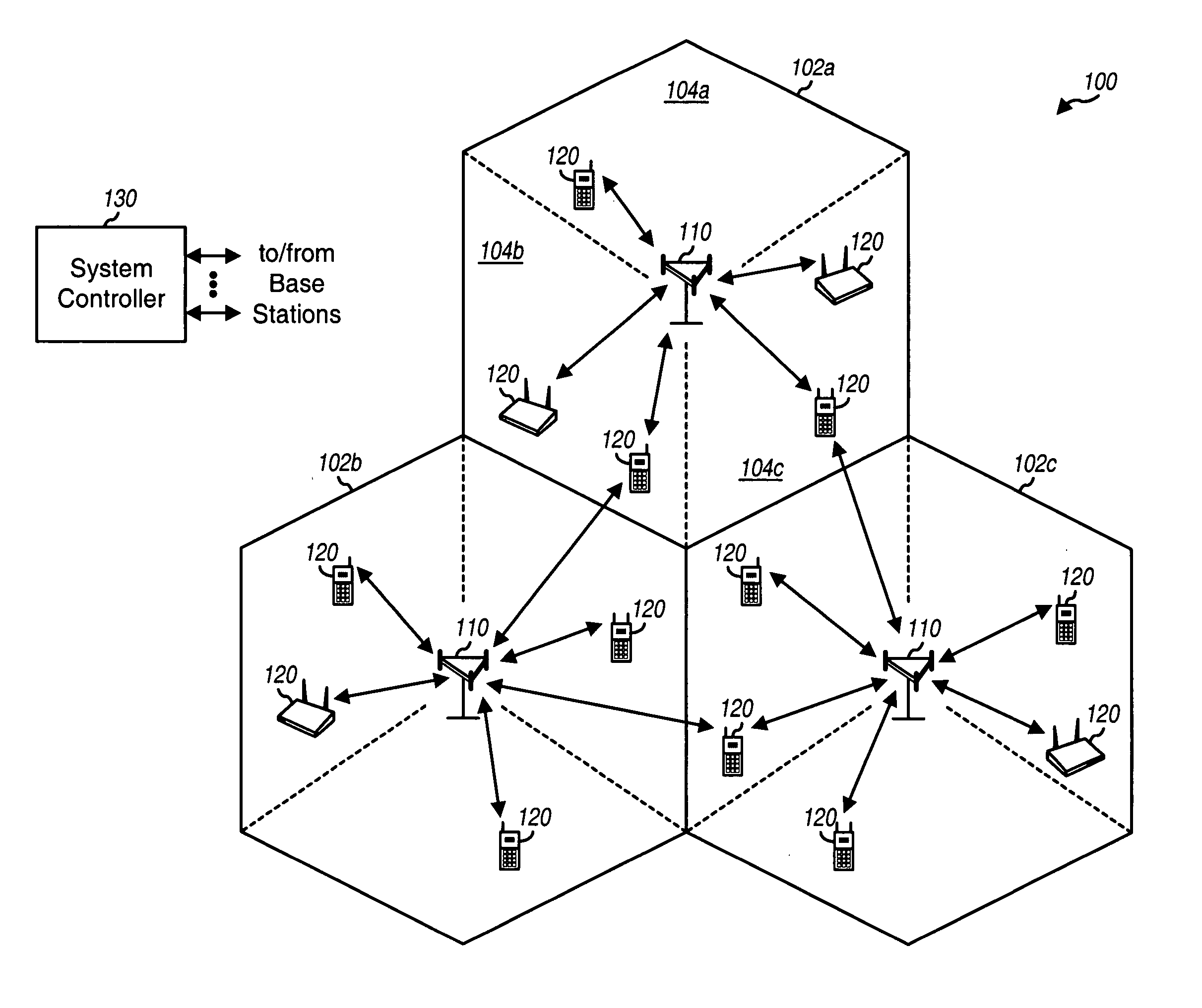
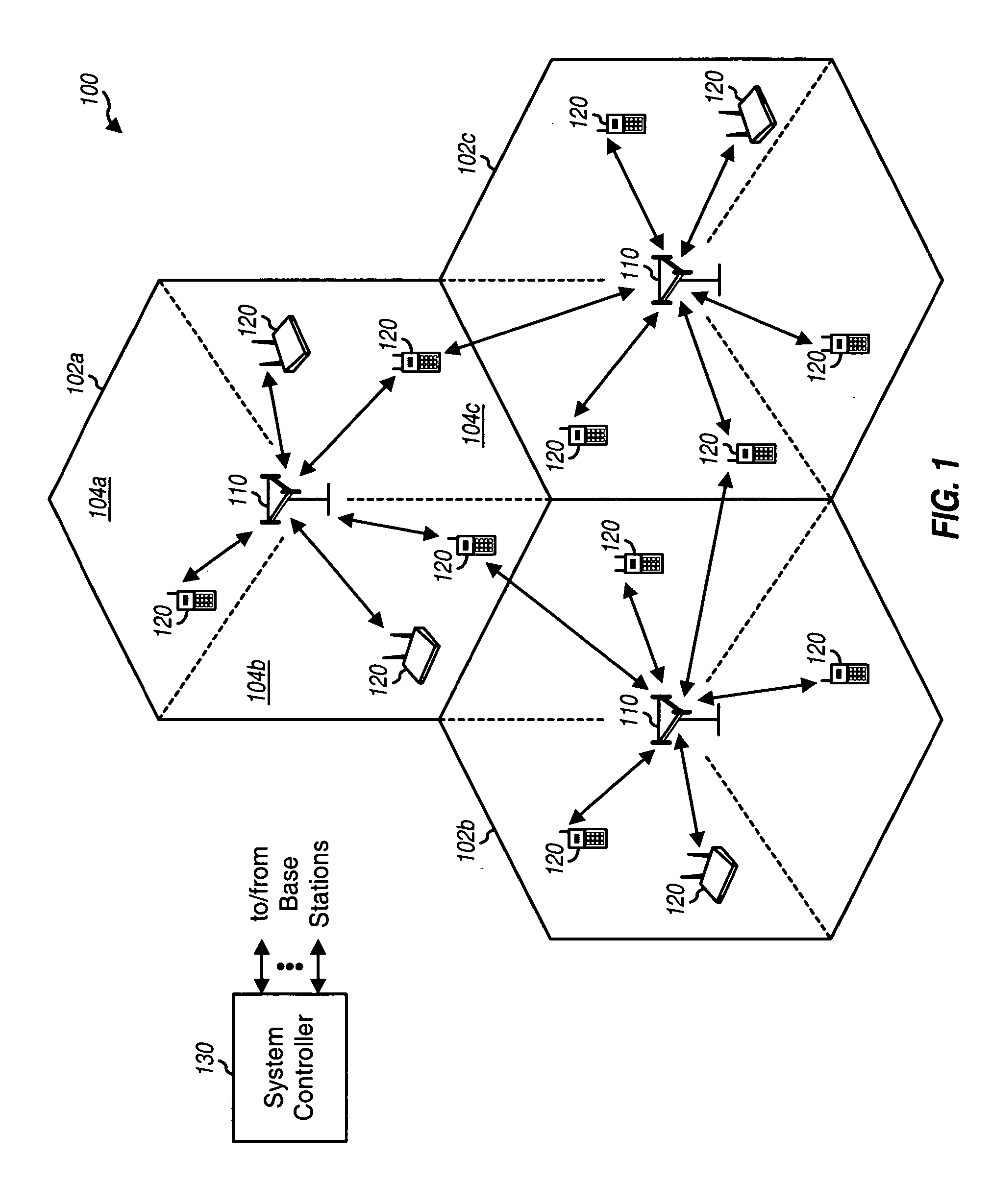
[0037]FIG. 1 shows a wireless communication system 100 with multiple base stations 110 and multiple terminals 120. A base station is generally a fixed station that communicates with the terminals and may also be referred to as an access point, a Node B, a base transceiver subsystem (BTS), and / or some other terminology. Each base station 110 provides communication coverage for a particular geographic area 102. The term “cell” can refer to a base station and / or its coverage area depending on the context in which the term is used. To improve system capacity, a base station coverage area may be partitioned into multiple smaller areas, e.g., three smaller areas 104a, 104b, and 104c. The term “sector” can refer to a fixed station that serves a smaller are...


PUM


Abstract

Techniques for utilizing multiple carriers to substantially improve transmission capacity are described. For multi-carrier operation, a terminal receives an assignment of multiple forward link (FL) carriers and at least one reverse link (RL) carrier. The carriers may be arranged in at least one group, with each group including at least one FL carrier and one RL carrier. The terminal may receive packets on the FL carrier(s) in each group and may send acknowledgements for the received packets via the RL carrier in that group. The terminal may send channel quality indication (CQI) reports for the FL carrier(s) in each group via the RL carrier in that group. The terminal may also transmit data on the RL carrier(s). The terminal may send designated RL signaling (e.g., to originate a call) on a primary RL carrier and may receive designated FL signaling (e.g., for call setup) on a primary FL carrier.

Description

I. CLAIM OF PRIORITY UNDER 35 U.S.C. §119 [0001] The present application for patent claims priority to Provisional Application Ser. No. 60 / 666,461, entitled “METHOD AND APPARATUS FOR HIGH RATE DATA TRANSMISSION IN WIRELESS COMMUNICATIONS,” filed Mar. 29, 2005, assigned to the assignee hereof, and expressly incorporated herein by reference.BACKGROUND [0002] I. Field [0003] The present disclosure relates generally to communication, and more specifically to techniques for high rate data transmission. [0004] II. Background [0005] Wireless communication systems are widely deployed to provide various communication services such as voice, packet data, broadcast, messaging, and so on. These systems may be multiple-access systems capable of supporting communication for multiple users by sharing the available system resources. Examples of such multiple-access systems include Code Division Multiple Access (CDMA) systems, Time Division Multiple Access (TDMA) systems, Frequency Division Multiple...

Claims


Application Information

Patent Timeline
Patent Type & Authority Applications(United States)
IPC IPC(8): H04J3/08H04B7/14H04J1/10H04W72/54
CPCH04B1/707H04J11/00H04L1/0029H04L1/0057H04L1/1607H04L5/0007H04L5/0016H04L5/0044H04L5/0048H04L5/0053H04L5/006H04L5/0094H04L5/0057H04L5/005H04L1/0026H04L27/26H04J13/12H04J13/0048H04L5/0055
Inventor DAMNJANOVIC, ALEKSANDARODENWALDER, JOSEPH P.LUNDBY, STEIN ARNEWEI, YONGBIN
Owner QUALCOMM INC
Learn More