
Surgical marker clip and method for cholangiography

a marker clip and cholangiography technology, applied in the field of surgical marker clips and methods for cholangiography, can solve problems such as flat clip and damage to duct tissue, and achieve the effect of convenient visualization

Inactive Publication Date: 2006-10-05
DUFF MICHAEL
View PDF33 Cites 166 Cited by
  • Summary
  • Abstract
  • Description
  • Claims
  • Application Information

AI Technical Summary

Benefits of technology

[0009] In accordance with the present invention as embodied and described herein, a surgical marker clip is provided which, upon placement about the cystic duct prior to cholangiography or cholecystectomy creates a radiopaque marker and identifier for the visual distinction of the common bile duct from the cystic duct, or other ducts. The marker clips are sized to the duct to be marked and are removably fastened about the outer wall of the duct with enough compression for frictional retention, but not so much compression so as to cause harm or injury to the duct being marked. The clips are preferably radiopaque so they can easily be visualized post-cholangiography on x-rays. It is also preferable to use two clips spaced apart to define the work area on the cystic duct for the cholecystectomy.

Problems solved by technology

The described clip, when used in the preferred applicator tool, is not compressed in the known clamping manner which results in a flattened clip which may damage duct tissue.

Method used


Image

  • Surgical marker clip and method for cholangiography
  • Surgical marker clip and method for cholangiography
  • Surgical marker clip and method for cholangiography

Examples


first embodiment

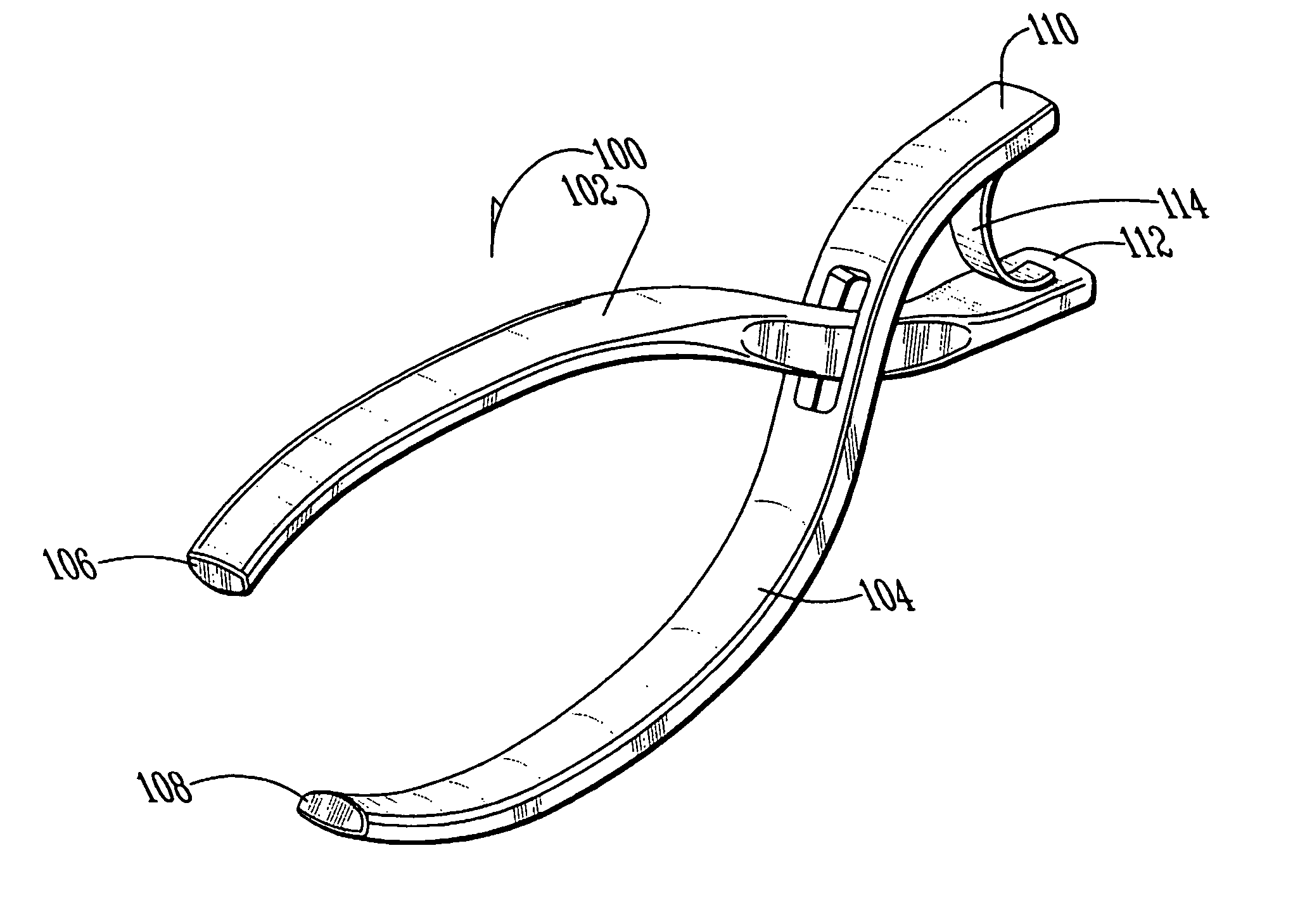
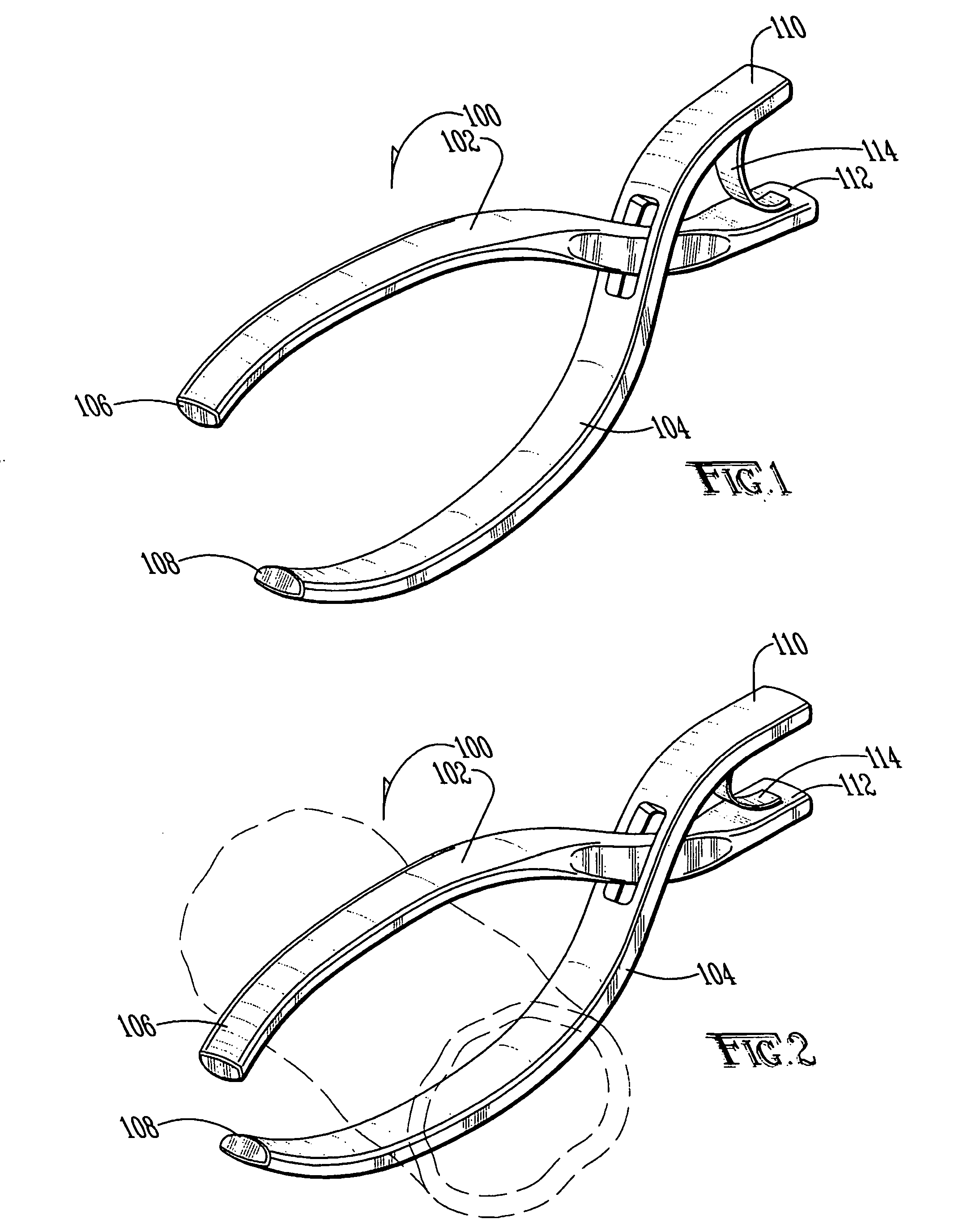
[0022] As shown in FIGS. 1 and 2, the marker clip 100 has two opposed arms 102 and 104 axially displaced from each other, and further having first ends 106 and 108, second ends 110 and 112 and being further pivotally connected intermediate the first ends 106, 108 and second ends 110, 112.

[0023] A spring 114 may be seated between the second ends 110 and 112 of the clip 100 so that inward compression of the second ends 110 and 112 compresses the spring 114 and causes the first arms, 102 and 104 to move outward away from each other somewhat akin to the actuation of scissors. The first arms 102 and 104 both have generally half-round or semi-annular sections configured to snugly fit about the outer wall of a duct without compressing the duct tissue as best shown in FIG. 2.

[0024] It is preferable that the clip can be operated using commercially available surgical instruments. The marker clip described above can be operated using available laparoscopic hemostats or other instruments capab...

second embodiment

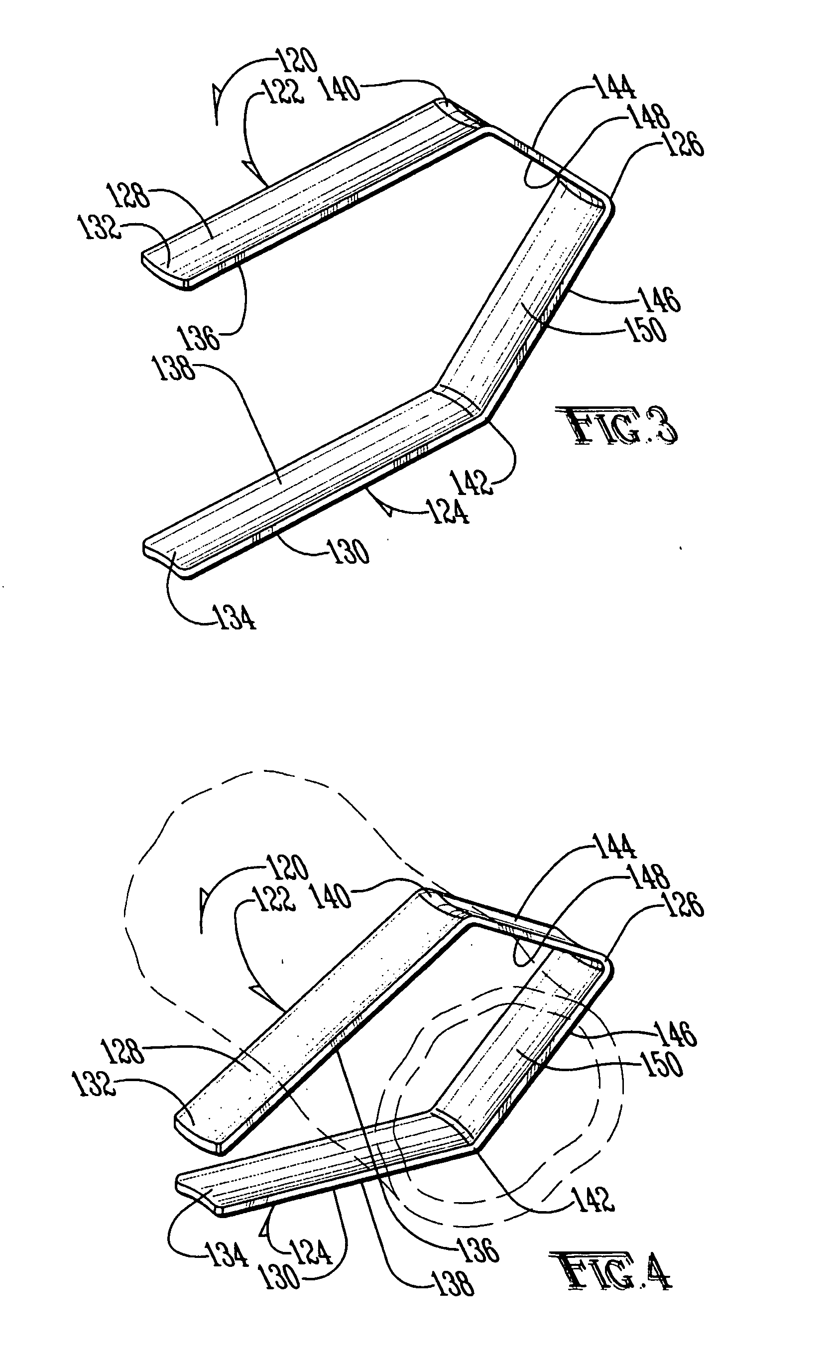
[0025] In the invention, the clip 120 comprises a simple compressingly fit member as shown in FIGS. 3 and 4. This clip 120 has a first leg 122 and a second leg 124 with an apex 126 therebetween. At the terminal end of the legs 122, 124, are spaced apart jaws 128, 130 which are generally open before it is positioned about the duct to be marked. The jaws 128, 130 each have distal ends 132, 134 which are spaced opposite one another with each jaw having a facing surface 136, 138 which may be configured to provide a grasping surface to increase frictional engagement with the outer surface of the duct to which it is applied. The marker clip 120 is positioned by passing the duct to be marked between the spaced apart jaws 128, 130 and substantially encircling the duct by biasing the jaws 128, 130 together with compressing force. The tensile of the marker clip 120 allows it to be compressed about the duct without crushing or overtly compressing the duct walls. It is preferred that each leg 1...


PUM


Abstract

A surgical marker clip and method for enhancing the safe performance of a cholangiography and cholecystectomy is disclosed. The clips are configured to frictionally engage the outer surface of the duct and are retained in place by light clamping force without damaging the duct. Placement of the clips allows a physician to visually isolate the common bile duct from the cystic duct during laparoscopic procedures which reduces bile duct injury typically caused by misidentification or visual misperception of the anatomy during the procedure.

Description

RELATED APPLICATIONS [0001] This application claims the priority to U.S. Patent Application Ser. No. 60 / 666,535 filed Mar. 30, 2005, the disclosure of which is incorporated herein by reference.BACKGROUND OF THE INVENTION [0002] One of the most commonly performed elective abdominal surgical procedures is the cholecystectomy for the removal of the gallbladder. It is estimated that more than 750,000 cholecystectomys are performed a year in the United States alone. Because this procedure is commonly performed laproscopically, surgeons often depend on preoperative imaging of the surgery site. A common technique is the use of intraoperative cholangiography which involves the injection of radiographic contrast material through the gall bladder into the cystic duct. The contrast material facilitates visual evaluation of the common bile duct. Injury to the common bile duct during these laparoscopic procedures is one of the leading medical malpractice claims against general surgeons. [0003] I...

Claims


Application Information

Patent Timeline
IPC IPC(8): A61B17/08
CPCA61B17/122A61B17/1285A61B17/1227
Inventor DUFF, MICHAEL
Owner DUFF MICHAEL
Learn More