Guide wire locking mechanism for rapid exchange and other catheter systems

Active Publication Date: 2006-10-05
ABBOTT CARDIOVASCULAR
View PDF18 Cites 11 Cited by
  • Summary
  • Abstract
  • Description
  • Claims
  • Application Information

AI Technical Summary

Benefits of technology

[0010] The housing portion has sufficient strength to impart an inward radial force that compresses the filtering device to its smaller diameter permitting the filter device to be subsequently removed from the patient. Once the filtering device is drawn into the housing portion of the catheter, it will be “encapsulated” to prevent emboli trapped in the filter basket from “back washing” into the body vessel, thus preventing the re-release of potentially damaging emboli into the patient's vasculature. The locking mechanism of the present invention prevents the guide wire and housing portion from moving relative to each other to maintain the filtering device “encapsulated” by the housing portion as the guide wire and catheter are simultaneously removed from the patient.
[0011] In another aspect of the present invention, the locking mechanism may include an opening which receives a portion of the guide wire. A motion-limiting component which

Problems solved by technology

Unfortunately, when a stenting or angioplasty procedure is performed in a highly vulnerable artery, such as the carotid artery, there is always a possibility that plaque could break away from the area of stenosis and enter the bloodstream.
The deposits or plaque may also rupture and form blood clots or thrombi that can completely obstruct blood flow in the affected artery or break free and travel, emboli, to another part of the body.
If the artery or arteries affected supply blood to a limb or appendage, gangrene could possibly result.
If the artery or arteries affected supply blood to the kidney or the kidneys, renal ischemia, infarction or renal failure could possibly result.
During the recovery step, there is a possibility that trapped embolic debris can backflow through the inlet opening

Method used


Image

  • Guide wire locking mechanism for rapid exchange and other catheter systems
  • Guide wire locking mechanism for rapid exchange and other catheter systems
  • Guide wire locking mechanism for rapid exchange and other catheter systems

Examples


Embodiment Construction

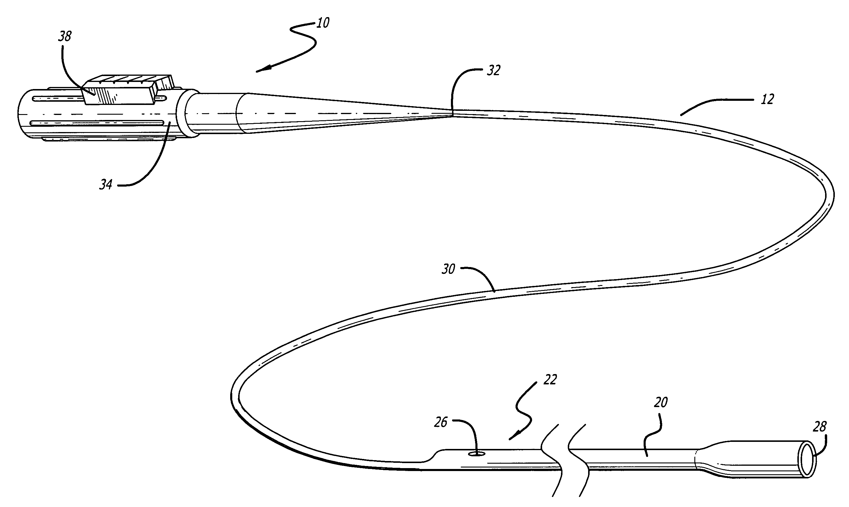
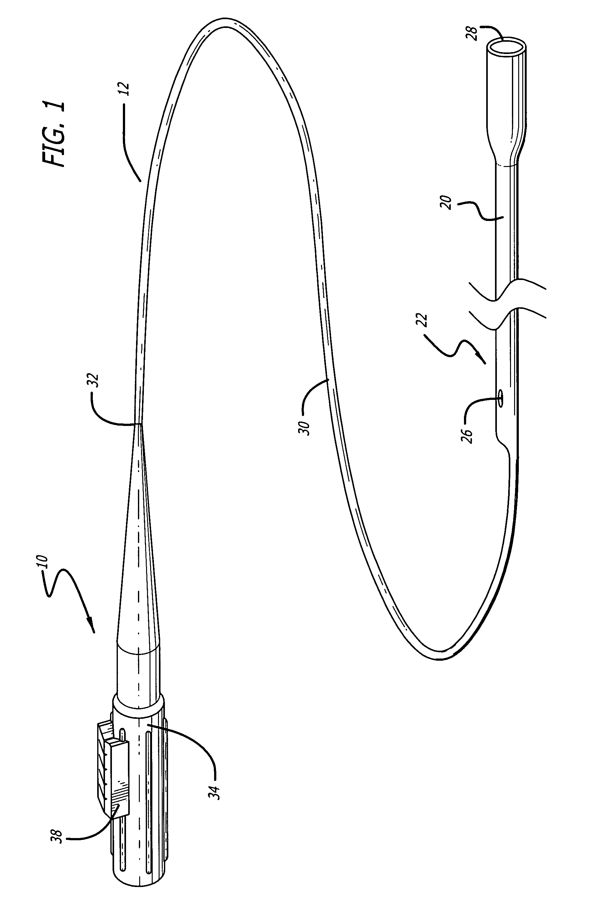
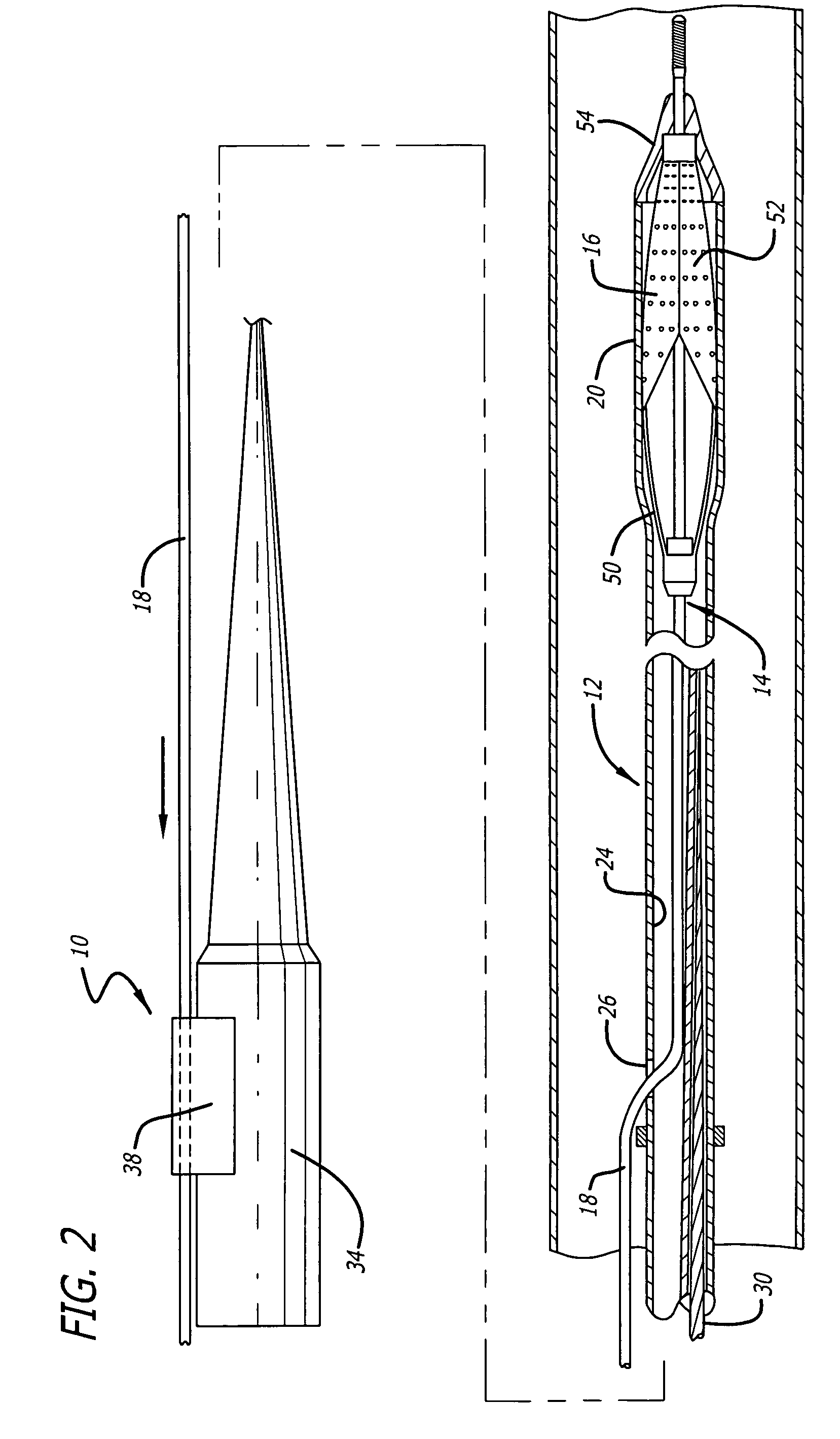
[0020] Turning now to the drawings, in which like reference numerals represent like or corresponding elements in the drawings, FIGS. 1 and 2 illustrate a locking mechanism 10 used with a recovery catheter 12 which incorporate features of the present invention. This recovery catheter 12 is adapted for use with a medical device such as an expandable embolic filter device 14 designed to capture embolic debris that may be created and released into a body vessel during an interventional procedure. The recovery catheter 12 and locking mechanism 10 can be used to recover the filtering portion 16 of the embolic filter device 14 while holding the guide wire 18 in place to prevent relative movement between the recovery catheter 12 and guide wire 18 as these devices are being simultaneously retrieved from the patient.

[0021]FIGS. 1 and 2 show a particular embodiment of a recovery catheter 12 that utilizes rapid-exchange technology to allow for quick advancement along the guide wire 18. The rec...


PUM


Abstract

A guide wire locking mechanism for a catheter system includes a motion-limiting component adapted to contact a portion of a guide wire and limit the direction of motion that the guide wire can slide therethrough. The motion-limiting component allows the guide wire to slide in one direction when placed in the locking mechanism but prevents the guide wire from moving in the opposite direction. The motion-limiting component can be made from a row of movable teeth having contact surfaces or faces which come in contact with a portion of the guide wire. The teeth are bendable to allow the guide wire to move in one direction but will tighten against the guide wire if one attempts to move the guide wire in an opposite direction. The guide wire locking mechanism can be used with a recovery sheath that can be advanced over the guide wire to collapse an expandable filtering portion mounted on a guide wire. The locking mechanism helps to maintain the recovery catheter on the collapsed filtering portion to allow both the recovery catheter and the filtering device to be simultaneously removed from the patient's vasculature, thus preventing the possibility that the recovery catheter can somehow be retracted off the filtering portion during removal.

Description

BACKGROUND OF THE INVENTION [0001] The present invention relates generally to catheters for use in conjunction with specialized medical devices, such as embolic filtering systems used when an interventional procedure is being performed in a stenosed or occluded region of a body vessel to capture embolic material that may be created and released into the vessel during the procedure. Additionally, the present invention can be used in conjunction with other medical delivery catheters utilized in body vessels. [0002] Numerous procedures have been developed for treating occluded blood vessels to allow blood to flow without significant obstruction. Such procedures usually involve the percutaneous introduction of an interventional device into the lumen of the artery, usually through a catheter. One widely known and medically accepted procedure is balloon angioplasty in which an inflatable balloon is introduced within the stenosed region of the blood vessel to dilate the occluded vessel. St...

Claims


Application Information

Patent Timeline
IPC IPC(8): A61M29/00A61M5/178
CPCA61F2/013A61M25/01A61M2025/1056A61M2025/09125A61M2025/0183
Inventor FUNG, GREGORY W.BEI, NIANJIONG JOANNIKANOROV, ALEXANDERLAFLASH, DANIELLE D.
Owner ABBOTT CARDIOVASCULAR
Why Eureka
Try Eureka