Power balancing signal combiner

a power balance and combiner technology, applied in the field of satellite receiver systems, can solve the problems of limiting the usefulness of this stacking feature, difficult and expensive to add new features, and reducing the service life of the combined signal,

Active Publication Date: 2006-10-05
DIRECTV LLC
View PDF99 Cites 37 Cited by
  • Summary
  • Abstract
  • Description
  • Claims
  • Application Information

AI Technical Summary

Benefits of technology

[0028] To minimize the limitations in the prior art, and to minimize other limitations that will become apparent upon reading and understanding the present specification, the present invention discloses systems for delivering satellite signals. An embodiment in accordance with the present invention comprises a receive antenna, including at least one low noise block amplifier (LNB), and a module, coupled to and proximate the receive antenna, the module comprising a multiswitch, coupled to the LNB, for directing the satellite signals received by the LNB to a plurality of outputs of the multiswitch, a plurality of tuners, respectively coupled to the outputs of the multiswitch, for tuning to a plurality of specific portions of the satellite signals in a respective fashion, the specific portions of the satellite signals selected based on commands received from a plurality of receivers, and an interface for delivering the specific portions of the satellite signals to the plurality of receivers, wherein the specific portions of the satellite signals are combined into a single combined signal and delivered to the plurality of receivers on a single output of the interface.

Problems solved by technology

However, current IRD 112 and system 100 designs cannot tune across this entire frequency band, which limits the usefulness of this stacking feature.
However, as mentioned above, current IRDs 112 cannot use the information in some of the proposed frequencies used for downlink signals 120, thus rendering useless the information transmitted in those downlink signals 120.
Such limitations on the related art make it difficult and expensive to add new features, such as additional channels, high-definition programming, additional satellite delivery systems, etc., or to add new IRD 112 units to a given house 110.

Method used


Image

  • Power balancing signal combiner
  • Power balancing signal combiner
  • Power balancing signal combiner

Examples


Embodiment Construction

[0046] In the following description, reference is made to the accompanying drawings which form a part hereof, and which show, by way of illustration, several embodiments of the present invention. It is understood that other embodiments may be utilized and structural changes may be made without departing from the scope of the present invention.

Overview

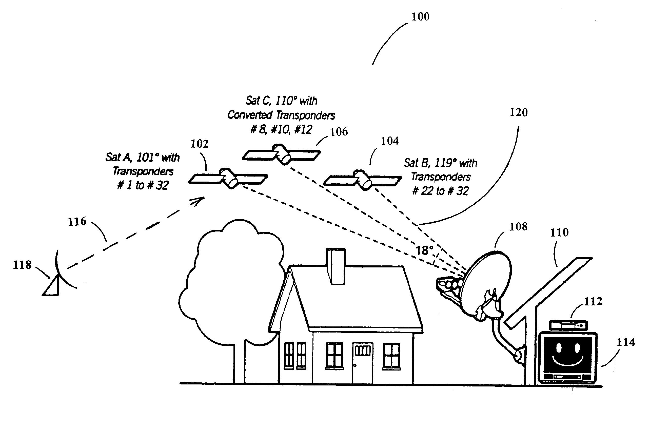
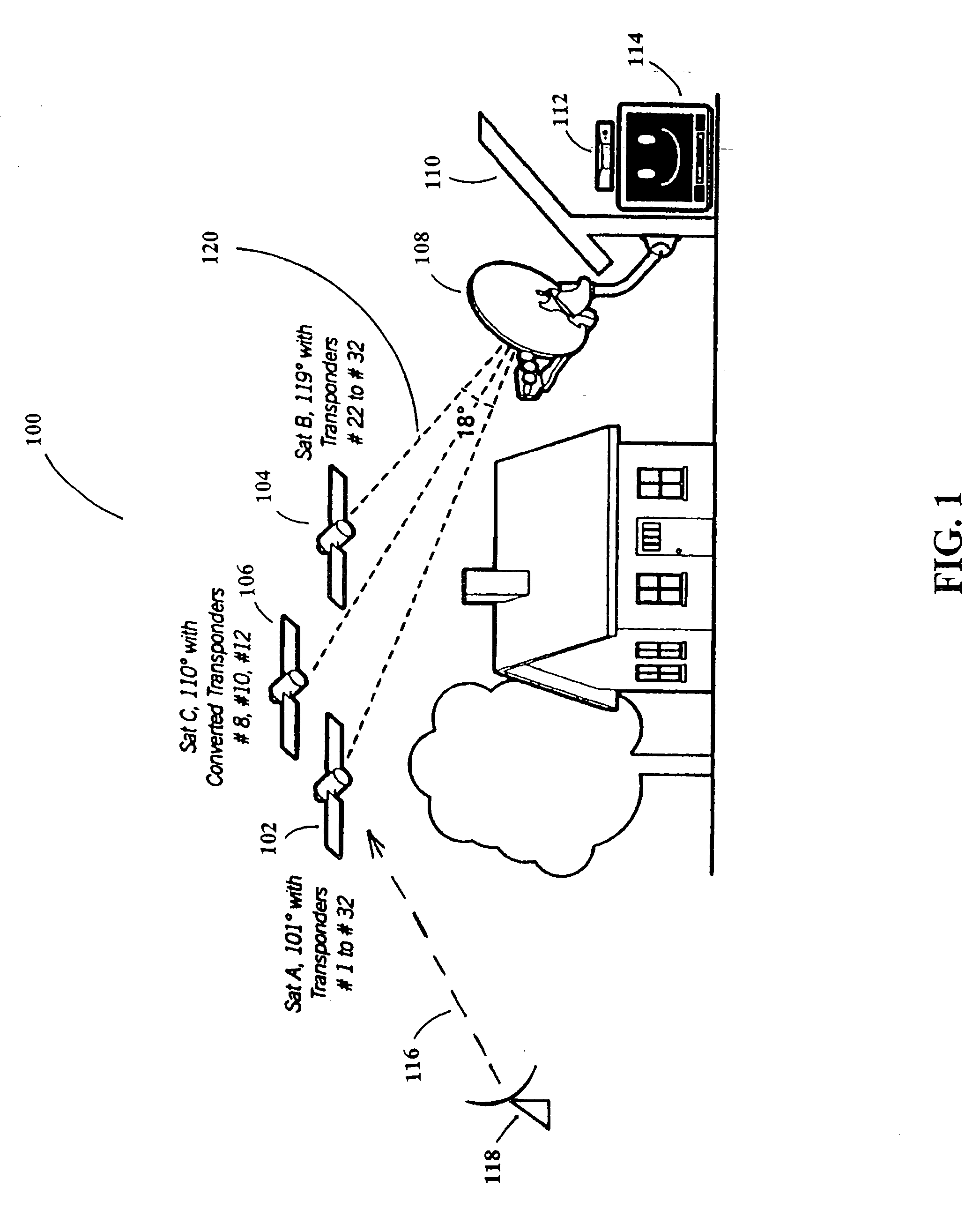
[0047] Currently, there are three orbital slots, each comprising one or more satellites, delivering direct-broadcast television programming signals. However, ground systems that currently receive these signals cannot accommodate additional satellite signals, and cannot process the additional signals that will be used to transmit high-definition television (HDTV) signals. The HDTV signals can be broadcast from the existing satellite constellation, or broadcast from the additional satellite(s) that will be placed in geosynchronous orbit. The orbital locations of the satellites are fixed by regulation as being separated by nine degrees,...


PUM


Abstract

Multiple systems for delivering satellite signals are described. An embodiment in accordance with the present invention comprises a receive antenna, including at least one low noise block amplifier (LNB), and a module, coupled to and proximate the receive antenna, the module comprising a multiswitch, coupled to the LNB, for directing the satellite signals received by the LNB to a plurality of outputs of the multiswitch, a plurality of tuners, respectively coupled to the outputs of the multiswitch, for tuning to a plurality of specific portions of the satellite signals in a respective fashion, the specific portions of the satellite signals selected based on commands received from a plurality of receivers, and an interface for delivering the specific portions of the satellite signals to the plurality of receivers, wherein the specific portions of the satellite signals are combined into a single combined signal and delivered to the plurality of receivers on a single output of the interface.

Description

CROSS-REFERENCE TO RELATED APPLICATIONS [0001] This application is related to the following co-pending and commonly-assigned applications: [0002] Application Ser. No. ______, filed on same date herewith, by Thomas H. James and Dipak M. Shah, entitled “SYSTEM ARCHITECTURE FOR CONTROL AND SIGNAL DISTRIBUTION ON COAXIAL CABLE,” attorneys' docket number PD-203014; [0003] Application Ser. No. ______, filed on same date herewith, by Thomas H. James and Dipak M. Shah, entitled “BACKWARDS-COMPATIBLE FREQUENCY TRANSLATION MODULE FOR SATELLITE VIDEO DELIVERY,” attorneys' docket number PD-204057; [0004] Application Ser. No. ______, filed on same date herewith, by Thomas H. James and Dipak M. Shah, entitled “TRANSPONDER TUNING AND MAPPING,” attorneys' docket number PD-204058; [0005] Application Ser. No. ______, filed on same date herewith, by Thomas H. James and Dipak M. Shah, entitled “AUTOMATIC LEVEL CONTROL FOR INCOMING SIGNALS OF DIFFERENT SIGNAL STRENGTHS,” attorneys' docket number PD-2040...

Claims


Application Information

Patent Timeline
Patent Type & Authority Applications(United States)
IPC IPC(8): H04N7/20
CPCH01Q1/125H01Q1/247H01Q19/17H04B7/18523H01Q5/45H04H40/90H04N7/20H04N21/6143H04H20/63
Inventor JAMES, THOMAS H.SHAH, DIPAK M.
Owner DIRECTV LLC
Why Eureka
Try Eureka