
Method of transferring a substrate

a substrate and module technology, applied in the direction of charge manipulation, packaging goods, furniture, etc., can solve the problems of contaminating the substrate received in the foup and the semiconductor substrate being transferred by the substrate transfer robot, affecting the effect of the substrate, and reducing the amount of purge gas used in the substrate transfer modul

Inactive Publication Date: 2006-10-12
SAMSUNG ELECTRONICS CO LTD
View PDF8 Cites 32 Cited by
  • Summary
  • Abstract
  • Description
  • Claims
  • Application Information

AI Technical Summary

Benefits of technology

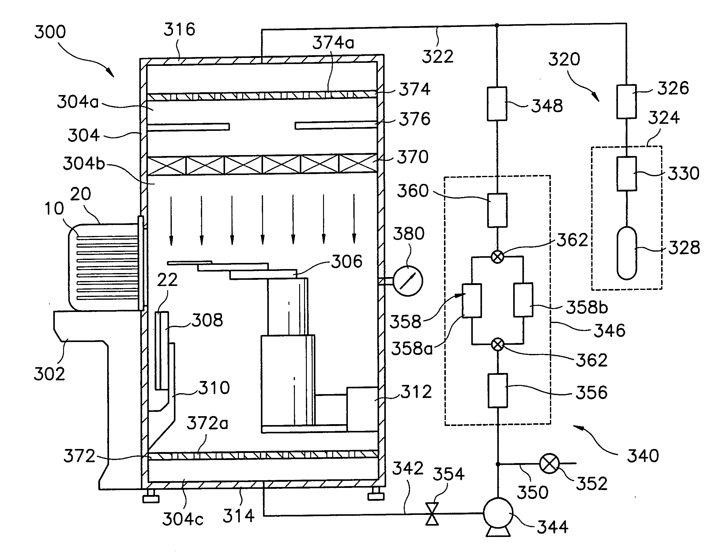
[0016] To solve these and other problems, the present invention provides a module for transferring a substrate that prevents the substrate from being contaminated by impurities including particles and airborne molecular contaminants during transfer of the substrate between a FOUP and a substrate process module.
[0030] The interior of the substrate transfer chamber is purged by the purge gas supplied from the gas supply unit and the resupplied purge gas from the contamination control unit, and thus impurities including particles and airborne molecular contaminants do not flow into the substrate transfer chamber. As a result, contamination of the substrate due to the impurities may be prevented.
[0031] In addition, the purge gas supplied into the substrate transfer chamber is circulated by means of the contamination control unit, and thus an amount of the purge gas used in the substrate transfer module may be reduced.

Problems solved by technology

When an internal pressure of the substrate transfer chamber is lower than a pressure of the clean room, the air in the clean room may flow back into the substrate transfer chamber, so that the semiconductor substrates received in the FOUP and the semiconductor substrate being transferred by the substrate transfer robot may be contaminated.
However, the filter cannot remove airborne molecular contaminants, such as organic contaminants, contained in the external air being supplied into the substrate transfer chamber.
Such airborne molecular contaminants may cause various defects on the semiconductor substrate.

Method used


Image

  • Method of transferring a substrate
  • Method of transferring a substrate
  • Method of transferring a substrate

Examples


Embodiment Construction

[0037] Korean Patent Application No. 2003-8847, filed on Feb. 12, 2003, and entitled: “Module For Transferring A Substrate,” is incorporated by reference herein in its entirety.

[0038] The present invention will now be described more fully hereinafter with reference to the accompanying drawings, in which preferred embodiments of the invention are shown. The invention may, however, be embodied in different forms and should not be construed as limited to the embodiments set forth herein. Rather, these embodiments are provided so that this disclosure will be thorough and complete, and will fully convey the scope of the invention to those skilled in the art. Like numbers refer to like elements throughout.

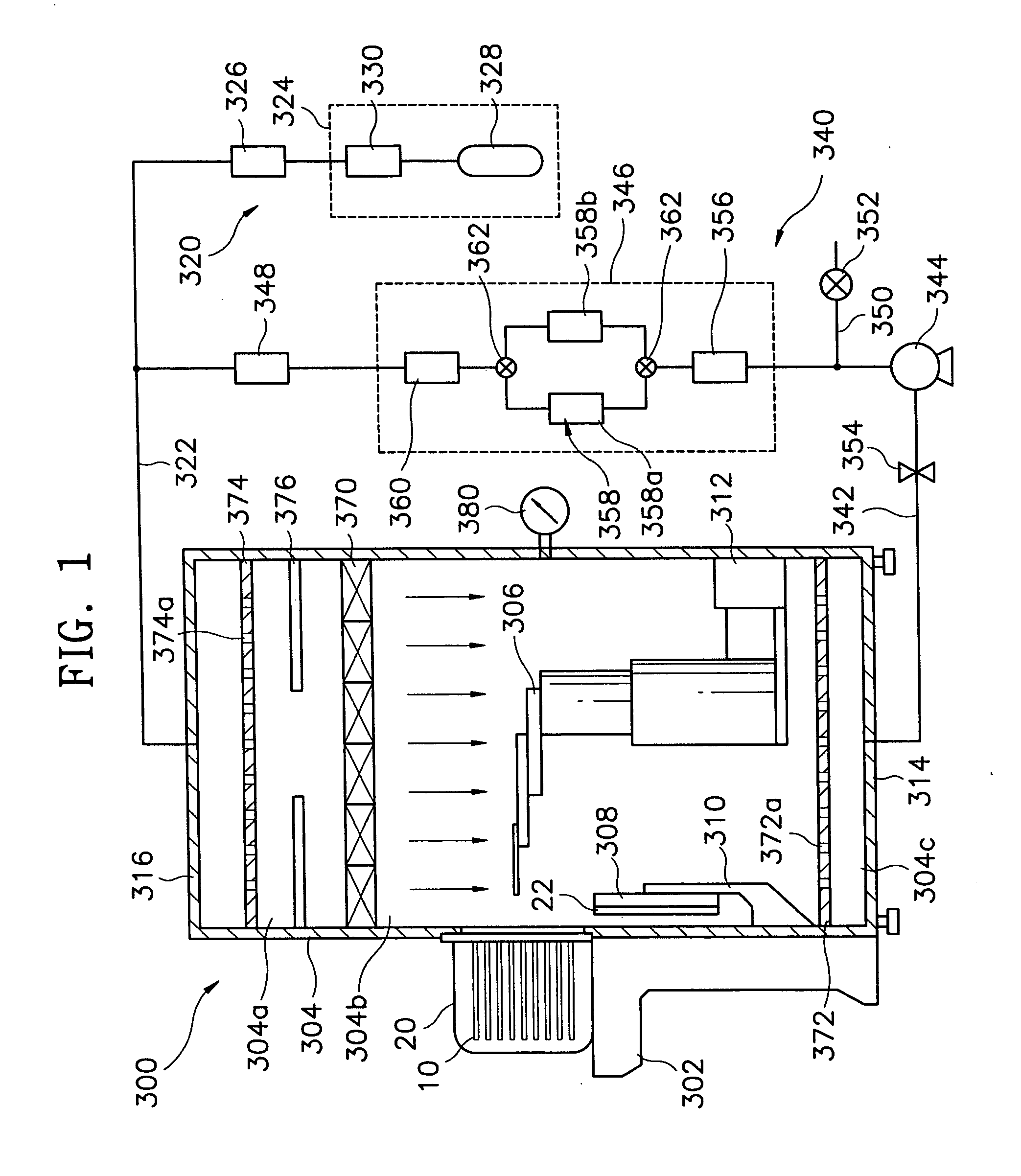
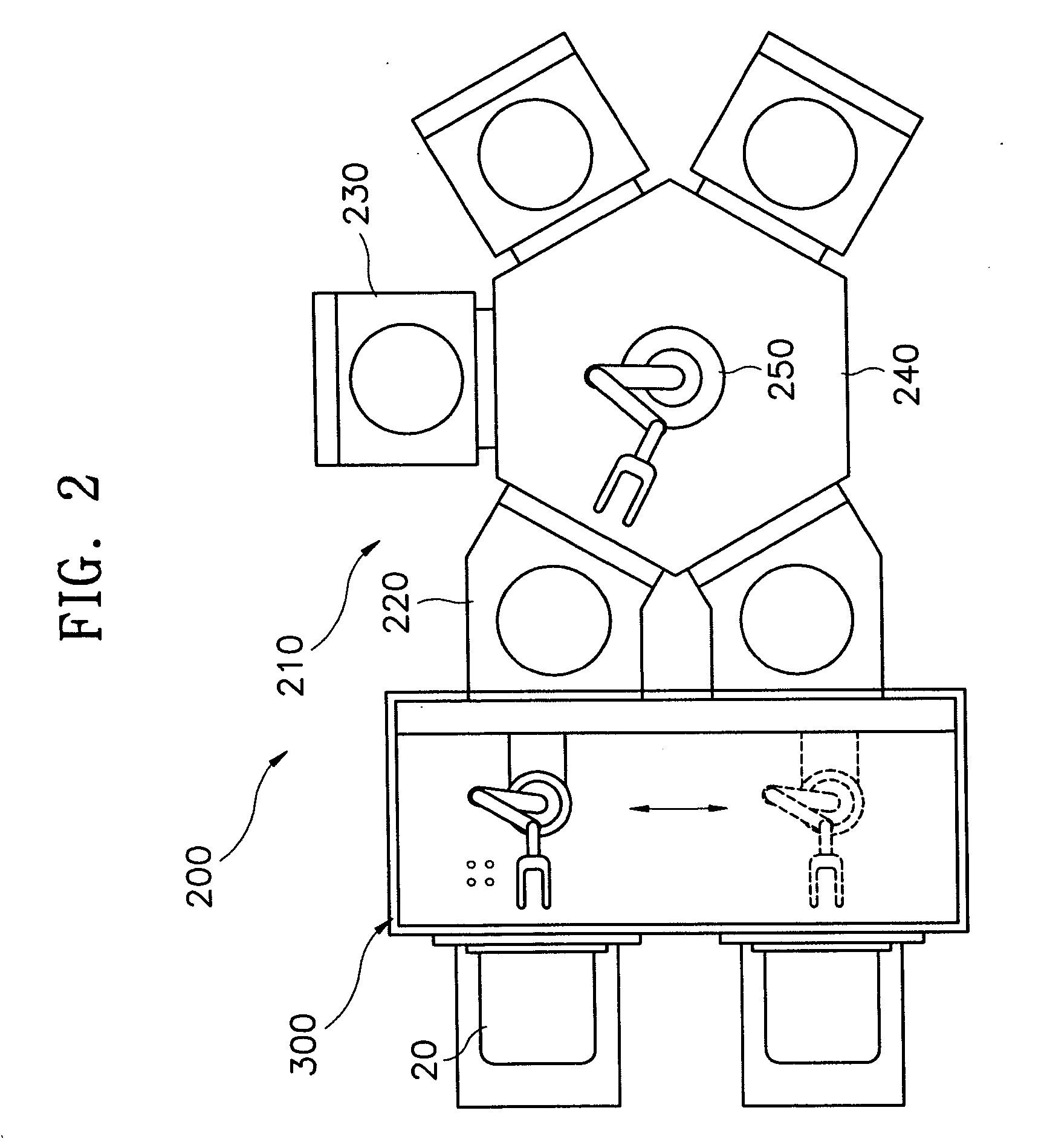
[0039]FIG. 1 illustrates a cross-sectional view of a module for transferring a substrate according to one embodiment of the present invention, and FIG. 2 illustrates a plan view of a substrate process apparatus having the substrate transfer module as shown in FIG. 1.

[0040] Referring t...


PUM


Abstract

A method of controlling contamination in a substrate transfer chamber that is disposed between a load port for supporting a container to receive a plurality of substrates and a substrate process module for processing the substrates includes supplying a purge gas into the substrate transfer chamber to purge an interior of the substrate transfer chamber, circulating the purge gas supplied into the substrate transfer chamber through a gas circular pipe, removing particles and airborne molecular contaminants from the purge gas being circulated, and resupplying the circulated purge gas into the substrate transfer chamber.

Description

CROSS REFERENCE TO RELATED APPLICATION [0001] This is a continuation application based on pending application Ser. No. 10 / 763,203, filed Jan. 26, 2004, the entire contents of which is hereby incorporated by reference.BACKGROUND OF THE INVENTION [0002] 1. Field of the Invention [0003] The present invention is related to a module for transferring a substrate. More particularly, the present invention is related to a module for transferring a substrate between a container to receive a plurality of substrates and a module for processing the substrate. [0004] 2. Description of the Related Art [0005] Generally, semiconductor devices are manufactured through a three-step process. First, a fabrication process is performed for forming electronic circuits on a silicon wafer used as a semiconductor substrate. Second, an electrical die sorting (EDS) process is performed for inspecting electrical characteristics of the semiconductor devices on the semiconductor substrate. Third, a packaging proce...

Claims


Application Information

Patent Timeline
Patent Type & Authority Applications(United States)
IPC IPC(8): F26B21/06H01L21/68B65B1/04B65G49/07H01L21/00H01L21/677
CPCH01L21/67017H01L21/67772H01L21/68
Inventor KIM, HYUN-JOOAHN, YO-HANHAM, DONG-SEOKKIM, JAE-BONG
Owner SAMSUNG ELECTRONICS CO LTD
Learn More