Method and Apparatus For Feeding Wire to a Welding Arc

a welding arc and wire technology, applied in the field of welding, can solve the problems of too much heating of workpieces, unstable process, and difficult control of arc length

Inactive Publication Date: 2006-10-12
ILLINOIS TOOL WORKS INC
View PDF60 Cites 98 Cited by
  • Summary
  • Abstract
  • Description
  • Claims
  • Application Information

AI Technical Summary

Problems solved by technology

However, the process can be unstable and control of the arc length can be difficult.
Also, for some application MIG can be too hot (cause too much heating of the workpiece).
Disadvantages of short circuit welding relate to the transitions between states, and instability of the process.
The pinching off at high current can result in a violent disintegration of the molten metal bridge producing excessive weld spatter.
These schemes share a common failure: they attempt to control both the energy of the weld and the transition between states using output current or power.
The net result is that the control schemes do not perform well at either controlling the energy into the weld or controlling the transition.
This system adequately controls the energy into the weld, but it does not provide independent control of the transitions between states.
However, a stepper motor does not necessarily provide adequate feeding of the wire over the long term.
One problem with controlled short circuit welding arises when the wire is retracted.
With nothing to compensate for the opposing forces, the wire might not feed in a smooth and efficient manner.
Another problem with controlled short circuit or pulse welding is that the prior art has not fully taken advantage of the process control made possible by the mechanical control of the state transitions.
The prior art has not adequately addressed the needs of short circuit or pulse welding at lower currents with thicker wires.
The difficult to implement control schemes, in particular, make it difficult to weld with thicker wire, such as 2.4 mm diameter wire, e.g., at low currents, such as less than 100 amps.
However, short arc lengths can result in inadvertent shorting of the wire to the weld pool.
Difficulties with spray processes include controlling the arc length and starting the process.

Method used


Image

  • Method and Apparatus For Feeding Wire to a Welding Arc
  • Method and Apparatus For Feeding Wire to a Welding Arc
  • Method and Apparatus For Feeding Wire to a Welding Arc

Examples


Embodiment Construction

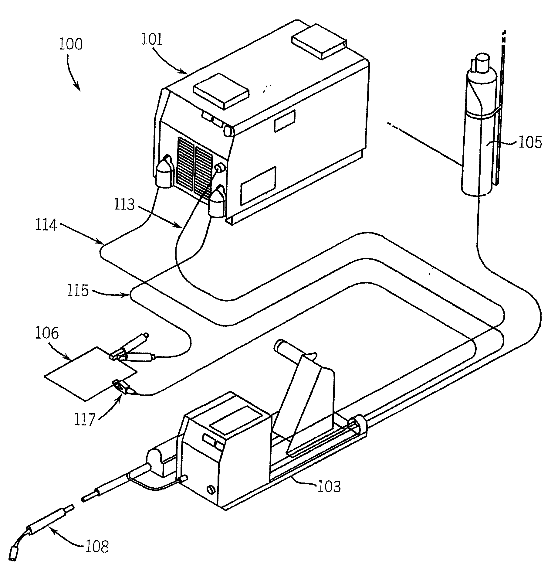
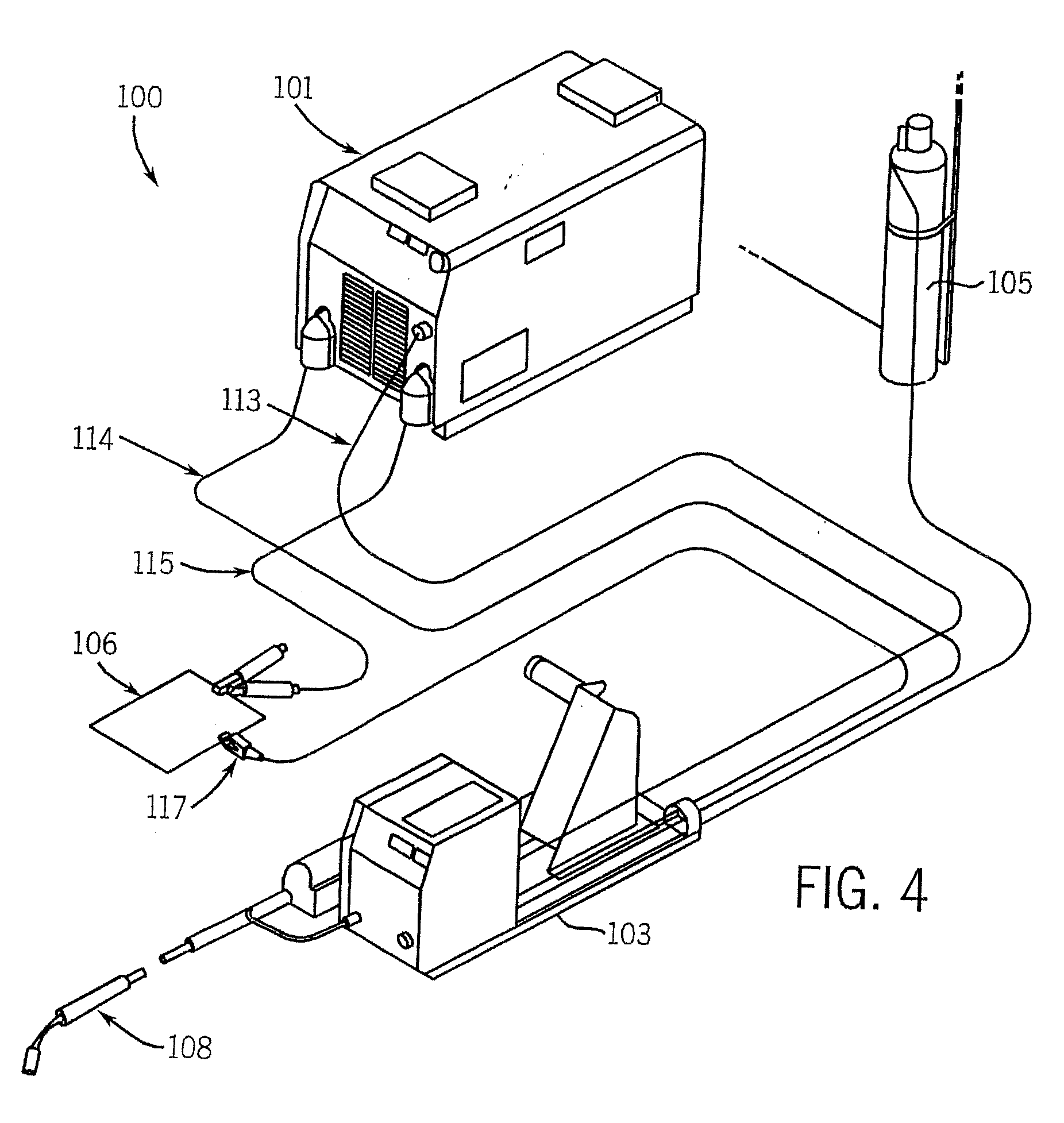
[0028] While the present invention will be illustrated with reference to a particular welding system using particular components, it should be understood at the outset that the invention may also be implemented with other systems, components, and modules, and be used in other environments.

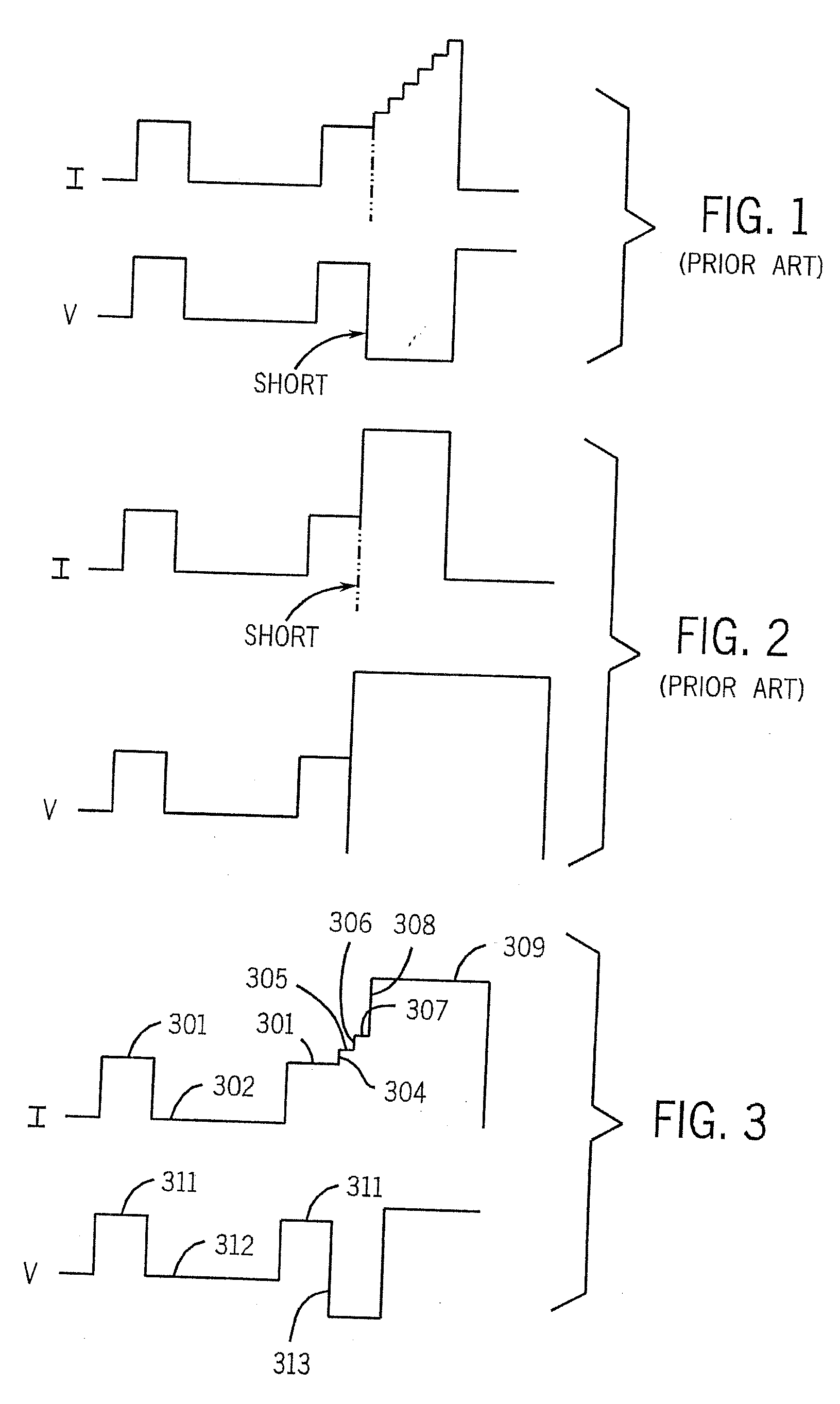
[0029] Generally, the present invention is a method and apparatus for controlled short circuit or pulse welding that includes mechanical control of transitions between the arc and short circuit states. In various embodiments the process includes a pulse mode or transfer. Control of energy to the weld is effected using the output current or voltage magnitude, wave shape, time, etc. Thus, the transitions are caused to occur by controlling the wire movement, and current can be coordinated with, the transitions to reduce spatter, instability, or other undesirable features, by, for example, changing the current as the transition occurs, or in anticipation of the transition. Alternatives include using t...


PUM

PropertyMeasurementUnit
movementaaaaaaaaaa
deposition ratesaaaaaaaaaa
arc lengthaaaaaaaaaa

Abstract

A method and apparatus for feeding wire in a welding system include one or more motors disposed adjacent the wire to drive it. A wire feed motor is also disposed along the wire path, and is closer to the source of wire than the torch, and closer to the source than the one or more motors. The motors may be a pair motors disposed on opposite sides of the wire and move the wire to and away from an arc end of a torch. They preferably reversing the direction of the wire within one process cycle. The or more motors may be a stepper motor, a servo motor, a zero backlash motor, a gearless motor, a planetary drive motor, or a linear actuator (such as a piston), in various embodiments.

Description

FIELD OF THE INVENTION [0001] The present invention relates generally to the art of welding. More specifically, it relates to welding using a short circuit or pulse process. BACKGROUND OF THE INVENTION [0002] There are many different arc welding processes used for numerous welding applications. While different processes share some characteristics, such as using an electric arc and / or current flow to provide the heat for the weld, different processes have characteristics that render them desirable for particular applications. [0003] MIG welding is a widely used process that gives high heat input into the wire electrode and the workpiece, and thus can give high deposition rates. However, the process can be unstable and control of the arc length can be difficult. Also, for some application MIG can be too hot (cause too much heating of the workpiece). The MIG process is often performed as a short circuit or pulse welding. [0004] Another known welding process is called controlled short c...

Claims


Application Information

Patent Timeline
Patent Type & Authority Applications(United States)
IPC IPC(8): B23K9/10B23K9/073B23K9/12B23K9/133B65H20/24
CPCB23K9/073B23K9/1336B23K9/124
Inventor HUISMANN, GERDHENEOKE, PETERHUTCHINSON, RICHARD M.ALBRECHT, BRUCE P.
Owner ILLINOIS TOOL WORKS INC
Why Eureka
Try Eureka