Optical scanner and image forming apparatus having the same
Active Publication Date: 2006-10-12
BROTHER KOGYO KK
View PDF4 Cites 10 Cited by
Summary
Abstract
Description
Claims
Application Information
AI Technical Summary
This helps you quickly interpret patents by identifying the three key elements:
Problems solved by technology
Method used
Benefits of technology
Benefits of technology
[0012] In general, a mirror portion is designed in shape to allow the mirror portion to receive light coming in the mirror portion, without overflow of light. In addition, as a dimension of a mirror portion in the rotation radial direction becomes larger, the moment of inertia of the mirror portion becomes larger, resulting in increasing difficulty in increasing a scan frequency of the mirror portion.
[0015] In view of the circumstances described above, the present invention is made for an object to provide an optical scanner for scanning incident light two-dimensionally by oscillatory rotation of a reflective surface on which light is incident and an image forming apparatus having the optical scanner, with a configuration of the optical scanner which more easily achieves an increase in scan rate of light and downsizing of the optical scanner.
Problems solved by technology
In addition, as a dimension of a mirror portion in the rotation radial direction becomes larger, the moment of inertia of the mirror portion becomes larger, resulting in increasing difficulty in increasing a scan frequency of the mirror portion.
Method used
Image
Click on the blue label to locate the original text in one second.
Reading with bidirectional positioning of images and text.
Examples
first embodiment
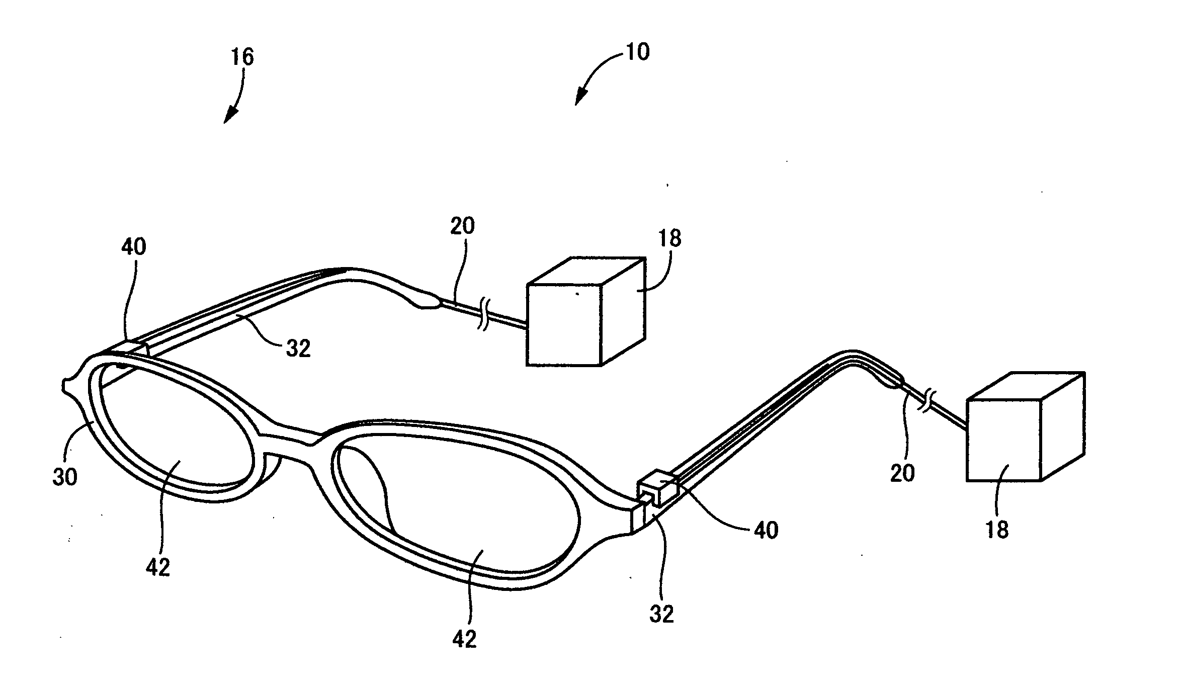
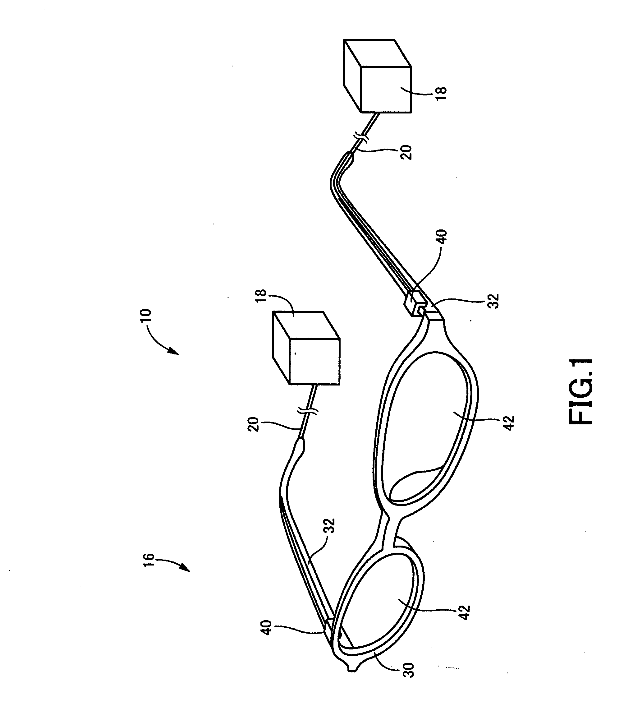
[0184]FIG. 1 illustrates schematically the exterior of a head-mounted type retinal scanning display device 10 (hereinafter, referred to as “RSD”) constructed in accordance with the present invention. This RSD 10 is adapted to project a beam of light onto a viewer's retina through a pupil of a viewer's eye, and to scan the beam of light on the retina, to thereby directly project an image onto the retina. In FIG. 3, reference numerals 12, 14 and 15 denote the eye, the pupil, and the retina, respectively. In the present embodiment, the retina 15 is an example of the “image-formed plane” set forth in the above mode (16).
[0185] As illustrated in FIG. 1, the RSD 10 includes amounted subsystem 16 mounted on a viewer's head in use, and a light source unit 18 worn on the viewer, both of which are physically separate from each other. The mounted subsystem 16 and the light source unit 18 are optically coupled with each other via a flexible optical fiber 20 as a light transmissive medium. In us...
second embodiment
[0252] Referring to FIG. 12, there is illustrated in exploded perspective view an optical scanner 292 in a head-mounted retinal scanning display device 290 (hereinafter, abbreviated as “RSD”) constructed in accordance with the present embodiment. The RSD 290, except for its components of the optical scanner 292, is in common in construction to the RSD 10 in accordance with the
[0253] As illustrated in FIG. 12, the optical scanner 292 in the present embodiment includes the cover 232 and the oscillating body 234, similarly with the second embodiment. The optical scanner 292, differently from the second embodiment, further includes a receiver 294.
[0254] The receiver 294, when the cover 232 and the oscillating body 234 are assembled, is detachably attached to an assembly 300 of the cover 232 and the oscillating body 234. As illustrated in FIG. 12, the receiver 294 in the shape of a flattened-box extends in its length direction. The receiver 294 includes: (a) an opening 302 and a bottom ...
fourth embodiment
[0265] Next, there will be described the present invention. FIGS. 14-22 illustrate a mirror unit 400 constructed in accordance with the present embodiment. As illustrated in FIG. 14, in the mirror unit 400, a scanning mirror 402 and an actuator 404 are disposed in a mirror support 406, the actuator 400 being adapted to actuate the scanning mirror 402 for its angular oscillation in directions indicated by the arrows labeled as “α” and “β” in this Figure.
[0266] The mirror unit 400 is optics angularly oscillating the scanning mirror 402 in a manner described above, to thereby reflect incoming light N impinging on the scanning mirror 402, into a direction depending on the angular position of the scanning mirror 402, as scanning light H. As illustrated in FIG. 15, the mirror unit 400 is configured so as to be detachably attached to a mirror-unit receiver 408.
[0267]FIG. 16 illustrates the mirror unit 400 when attached with the mirror-unit receiver 408 (when in use). In the present embodi...
PUM
Abstract
An optical scanner is disclosed which includes: a first scanning device having a first mirror portion in which a first reflective surface is formed, the first scanning device scanning in a first direction, light which impinges obliquely on the first reflective surface, by oscillatory rotation of the first mirror portion about a first oscillation axis; and a second scanning device having a second mirror portion in which a second reflective surface is formed so as to be generally in parallel to the first reflective surface in a non-active state of the optical scanner, the second scanning device scanning in a second direction intersecting with respect to the first direction, the light exiting the first reflective surface and then entering obliquely the second reflective surface, by oscillatory rotation of the second mirror portion about a second oscillation axis intersecting with respect to the first oscillation axis. The first oscillation axis is oriented substantially parallel to a direction in which the light enters the first reflective surface, when the optical scanner is viewed in a direction perpendicular to the first and second reflective surfaces.
Description
CROSS-REFERENCE TO RELATED APPLICATIONS [0001] This application is based on Japanese Patent Applications No. 2003-420487 filed Dec. 18, 2003 and No. 2003-397385 filed Nov. 27, 2003, and International Application No. PCT / JP2004 / 017379 filed Nov. 24, 2004, the contents of which are incorporated hereinto by reference. [0002] This is a continuation of International Application No. PCT / JP2004 / 017379 filed Nov. 24, 2004, which was published in Japanese under PCT Article 21(2).BACKGROUND OF THE INVENTION [0003] 1. Field of the Invention [0004] The invention relates to an optical scanner for scanning incident light two-dimensionally by oscillatory rotation of a reflective surface on which light is incident, and an image forming apparatus having such an optical scanner, and more particularly to improvements in construction of the optical scanner. [0005] 2. Description of the Related Art [0006] There is already known an optical scanner for scanning light, which is of a type in which incident ...
Claims
Application Information
Patent Timeline
Application Date:The date an application was filed.
Publication Date:The date a patent or application was officially published.
First Publication Date:The earliest publication date of a patent with the same application number.
Issue Date:Publication date of the patent grant document.
PCT Entry Date:The Entry date of PCT National Phase.
Estimated Expiry Date:The statutory expiry date of a patent right according to the Patent Law, and it is the longest term of protection that the patent right can achieve without the termination of the patent right due to other reasons(Term extension factor has been taken into account ).
Invalid Date:Actual expiry date is based on effective date or publication date of legal transaction data of invalid patent.

