Method and system for remotely detecting metal items, for example, weapons

Inactive Publication Date: 2008-05-08
DANILOV NIKOLAY YURIEVICH +1
View PDF48 Cites 2 Cited by
  • Summary
  • Abstract
  • Description
  • Claims
  • Application Information

AI Technical Summary

Benefits of technology

[0043] An increase in the scanning rate and reliability is attained in the proposed system owing to the desi

Problems solved by technology

A disadvantage of this method and the systems implementing it is that radiation should be manually directed to potentially suspicious objects, since the direction of electromagnetic-wave radiation in such systems is fixed.
Another disadvantage of these systems is that they do not display in a visual form the zone of the system operations and activities of the objects located within the zone (for example, the people located within the zone), which contain concealed metal items to be detected.
This disadvantage is due to the fact that these systems do not incorporate a video camera.
Two disadvantages are related to the use (in the case of the prototype of the system, in the system radar) of pulse or continuous electromagnetic radiation.
If pulse radiation is employed, dete

Method used


Image

  • Method and system for remotely detecting metal items, for example, weapons
  • Method and system for remotely detecting metal items, for example, weapons

Examples


Embodiment Construction

[0045] Description of the Proposed System

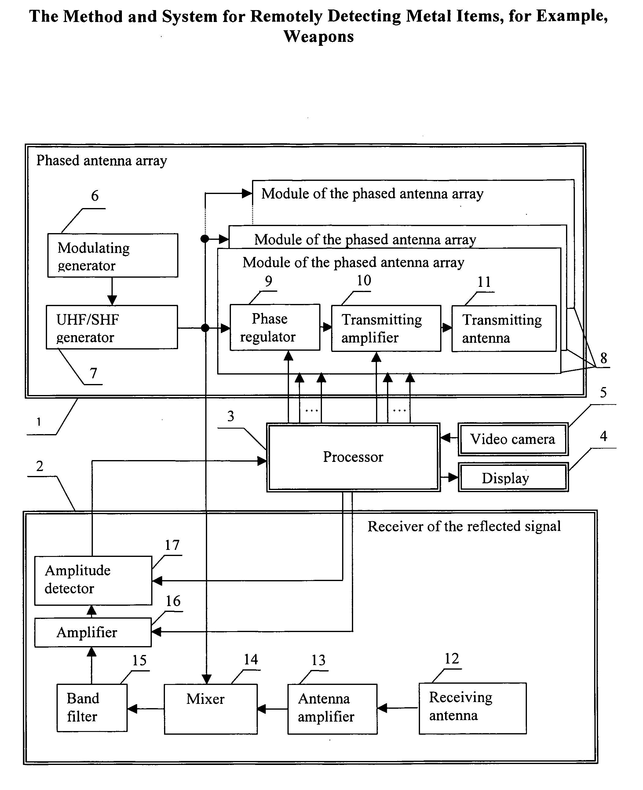
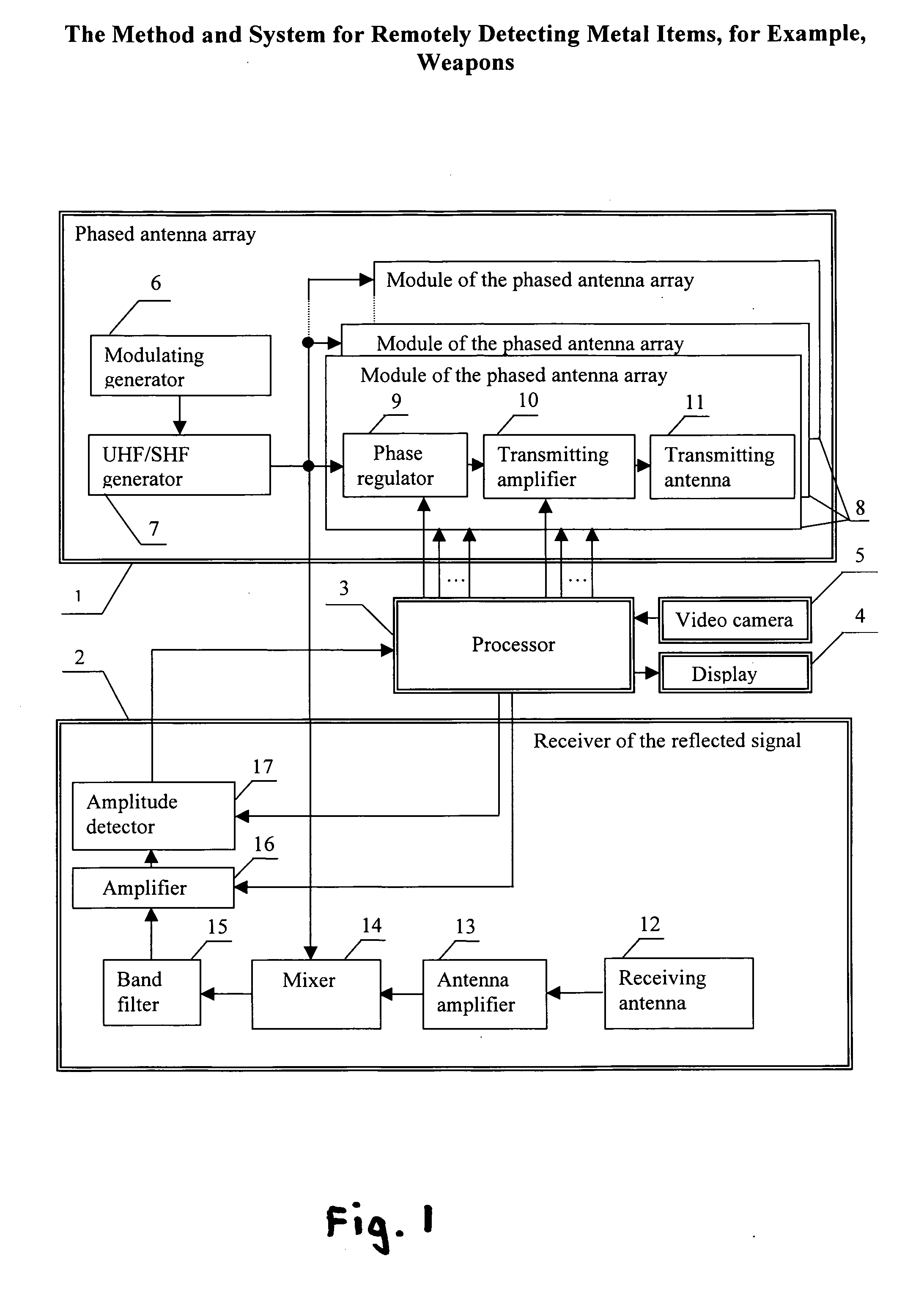
[0046] The present invention (the method and the system) may be implemented using the system whose functional flowchart is shown in the FIGURE.

[0047] The proposed system contains a phased antenna array 1 radiating a continuous frequency-modulated super high or ultra high frequency signal, a receiver of reflected signals 2, a processor 3, a display 4, and a video camera 5.

[0048] Ultra high frequency (UHF) is known to be characterized by the range of frequencies 300-3000 MHz and the super high frequency (SHF) by the range of frequencies 3-30 GHz (see, for example, the glossary of the Alliance for Telecommunications Industry Solutions, 2000, approved by the American National Standards Institute, http: / / www.atis.org / tg2k / t1g2k.html). The antenna array 1 radiates a signal belonging to the indicated UHF or SHF range.

[0049] The phased antenna array 1 contains a modulating generator 6, a UHF / SHF generator 7 whose input is connected to the output ...


PUM


Abstract

The invention relates to the methods and systems for remotely detecting metal items, for example, weapons, concealed in cloths or belongings and may be used in security complexes. The proposed system contains a phased antenna array 1 radiating a continuous frequency-modulated ultra high or super high frequency signal and scanning a controlled space, a receiver 2 of reflected signals, a processor 3, a display 4, and a video camera 5. The processor 3 detects a potentially threatening metal item during any scanning period other than the initial period if one of the two comparison conditions holds for some radiation direction: Ai>A0+Δ or Ai<A0−Δ where Ai is the code of the signal amplitude at the output of the receiver 2 of the reflected signal during any scanning period following the initial period for some radiation direction; A0 is the code of the signal amplitude at the same output for the same direction of radiation during the initial scanning period when no potentially threatening metal items are allowed in the scanning sector, and Δ>0 is the tolerance of the deviation of the code A0 taking into account permissible changes in the reflected signal. Advantages of the invention: extension of the range of permissible distances to detected metal items, increased noise immunity, simplified operator activities, and increased scanning rate and reliability.

Description

FIELD OF THE INVENTION [0001] The invention relates to the measuring technique or, more specifically, methods and systems for remotely detecting potentially threatening metal items, for example, weapons, and for visually observing the objects containing them. [0002] The invention may be used in security complexes, airports, stadiums, and other public gathering sites for detecting weapons concealed in clothes or belongings and for observing the individuals concealing the weapons. BACKGROUND OF THE INVENTION [0003] The proposed method and system for detection of metal items belong to the methods and devices based on reflection of electromagnetic waves (Int.Class7 G01S13). [0004] Known are methods and systems for remotely detecting metal item based on reflection of electromagnetic waves that do not use automatic scanning of the controlled space by electromagnetic radiation. Such systems comprise transmitting and receiving antennas, transmitting and receiving electronic apparatuses conn...

Claims


Application Information

Patent Timeline
IPC IPC(8): G01S13/00
CPCG01S13/04G01S13/89G01S13/887G01S13/88
Inventor DANILOV, NIKOLAY YURIEVICHKROPOTOV, VLADIMIR AVENIROVICH
Owner DANILOV NIKOLAY YURIEVICH
Why Eureka
Try Eureka