Photoelectric encoder and electronic equipment

Active Publication Date: 2006-10-12
SHARP KK
View PDF8 Cites 11 Cited by
  • Summary
  • Abstract
  • Description
  • Claims
  • Application Information

AI Technical Summary

Benefits of technology

[0115] In the photoelectric encoder of the light transmission type of the present invention, the light-transmitting portion and the light-shielding portion of the moving object alternately pass at the prescribed movement frequency between the light-emitting device and each of the light-receiving devices along one direction in which the light-receiving devices are arranged. In accordance with the passing of the light-transmitting portion and the light-shielding portion of the moving object sequentially through the position corresponding to the plurality of light-receiving devices, the output values of the plurality of light-receiving devices sequentially

Problems solved by technology

Therefore, minute frequency changes have conventionally been not able to be read, and there has been a limitation in improving the resolution during use.
However, if the slit width is narrowed as the slit pitch is reduced, the quantity of input light cannot be secured, and this leads to a reduction in the SN ratio (s

Method used


Image

  • Photoelectric encoder and electronic equipment
  • Photoelectric encoder and electronic equipment
  • Photoelectric encoder and electronic equipment

Examples


Embodiment Construction

[0154] The present invention will be described in detail below by the embodiments shown in the drawings.

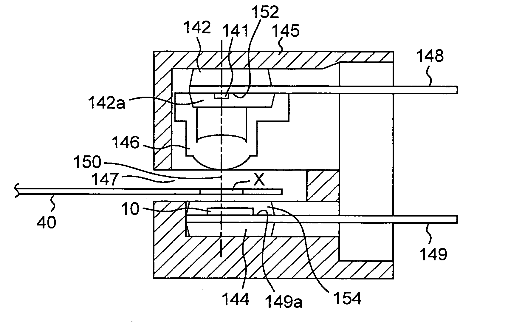
[0155]FIG. 10 shows the cross section of the detection section of the photoelectric encoder of the light transmission type of one embodiment. In the photoelectric encoder, a light-emitting section 142 is lodged on one side (upper side in FIG. 10) of a casing 145 that has a slot 147 at an approximate center, and a light-receiving section 144 is lodged on the other side (lower side in FIG. 10). With this arrangement, the light-emitting section 142 and the light-receiving section 144 face each other. The light-emitting section 142 is constituted by mounting a semiconductor light-emitting chip 141 that serves as a light-emitting device on a header portion 148a of a lead frame 148 and sealing the same with a transparent resin 152. The light-receiving section 144 is constituted by mounting a semiconductor light-receiving chip 10 that includes a plurality of light-receiving devices on t...


PUM


Abstract

The photoelectric encoder of the present invention has a light-emitting device and light-receiving devices arranged in one direction in a region that light from the light-emitting device can reach. When a moving object that alternately has a light-on portion that produces a state in which light is incident on the light-receiving device and a light-off portion that produces a state in which light is not incident on the light-receiving device passes at a prescribed movement frequency in the one direction, an output of each of the light-receiving devices takes a value corresponding to the incidence or nonincidence of light on the light-receiving device. A logical operating section carries out operation of the logical values expressed by the outputs of the light-receiving devices to form an output signal that has a frequency different from the movement frequency.

Description

CROSS-REFERENCE TO RELATED APPLICATIONS [0001] This Nonprovisional application claims priority under 35 U.S.C. §119(a) on Patent Applications No. 2005-109732 filed in Japan on Apr. 6, 2005, No. 2005-188541 filed in Japan on Jun. 28, 2005 and No. 2005-366734 filed in Japan on Dec. 20, 2005, the entire contents of which are hereby incorporated by reference. BACKGROUND OF THE INVENTION [0002] The present invention relates to photoelectric encoders. The present invention relates, in particular, to, for example, photoelectric encoders of a light transmission type and a light reflection type employing a moving object with a plurality of slits formed. [0003] The present invention also relates to electronic equipment provided with such a photoelectric encoder. The electronic equipment widely includes printing machines such as copying machines and printers and FA (Factory Automation) equipment such as robots. [0004] As this kind of photoelectric encoder, a light transmission type as shown in...

Claims


Application Information

Patent Timeline
IPC IPC(8): G01D5/34
CPCG01D5/3473G01D5/2451
Inventor OKADA, NORIKAZUKISHI, NORITAKAHIGASHI, KEIKO
Owner SHARP KK
Why Eureka
Try Eureka