Step motor

a step motor and step motor technology, applied in the direction of dynamo-electric machines, master clocks, magnetic circuit shapes/forms/construction, etc., can solve the problem of large amount of energy consumed at the time of starting the rotation, and achieve the effect of reducing power consumption, reducing magnetic fields, and saving energy

Active Publication Date: 2006-10-12
SEIKO INSTR INC
View PDF10 Cites 4 Cited by
  • Summary
  • Abstract
  • Description
  • Claims
  • Application Information

AI Technical Summary

Benefits of technology

[0008] It is an object of the present invention to solve the above-mentioned drawback and provide a step motor in which the power consumption can be suppressed at the time of starting rotation of the rotor.
[0009] According, to another aspect of the present invention, there is provided a step motor including a rotor having four magnetic poles; a first magnetic pole magnetically excited by a first coil; a second magnetic pole magnetically excited by a second coil; and a third magnetic pole magnetically excited by the first coil and the second coil. A gap between the third magnetic pole and the rotor is smaller than that between the first magnetic pole and the rotor and that between the second magnetic pole and the rotor. According to the present invention, the gap between the third magnetic pole and the rotor is smaller than that between the first magnetic pole and the rotor and that between the second magnetic pole and the rotor. By employing such configuration, the effect of the magnetic field can be intensified from the third magnetic pole to the rotor having four magnetic poles. Accordingly, it is possible to relatively weaken the magnetic fields set up from the first magnetic pole and the second magnetic pole, which tend to intensify the influence on the rotor, enabling the power consumption to be reduced at the time of starting the rotation of the rotor. Thus, it is possible to provide the step motor, which can save energy and consume less power and generate a high drive torque at the time of starting the rotation.

Problems solved by technology

Therefore, the above-described step motor 100 has a drawback that a large amount of energy is consumed at the time of starting the rotation.

Method used


Image

  • Step motor
  • Step motor
  • Step motor

Examples


Embodiment Construction

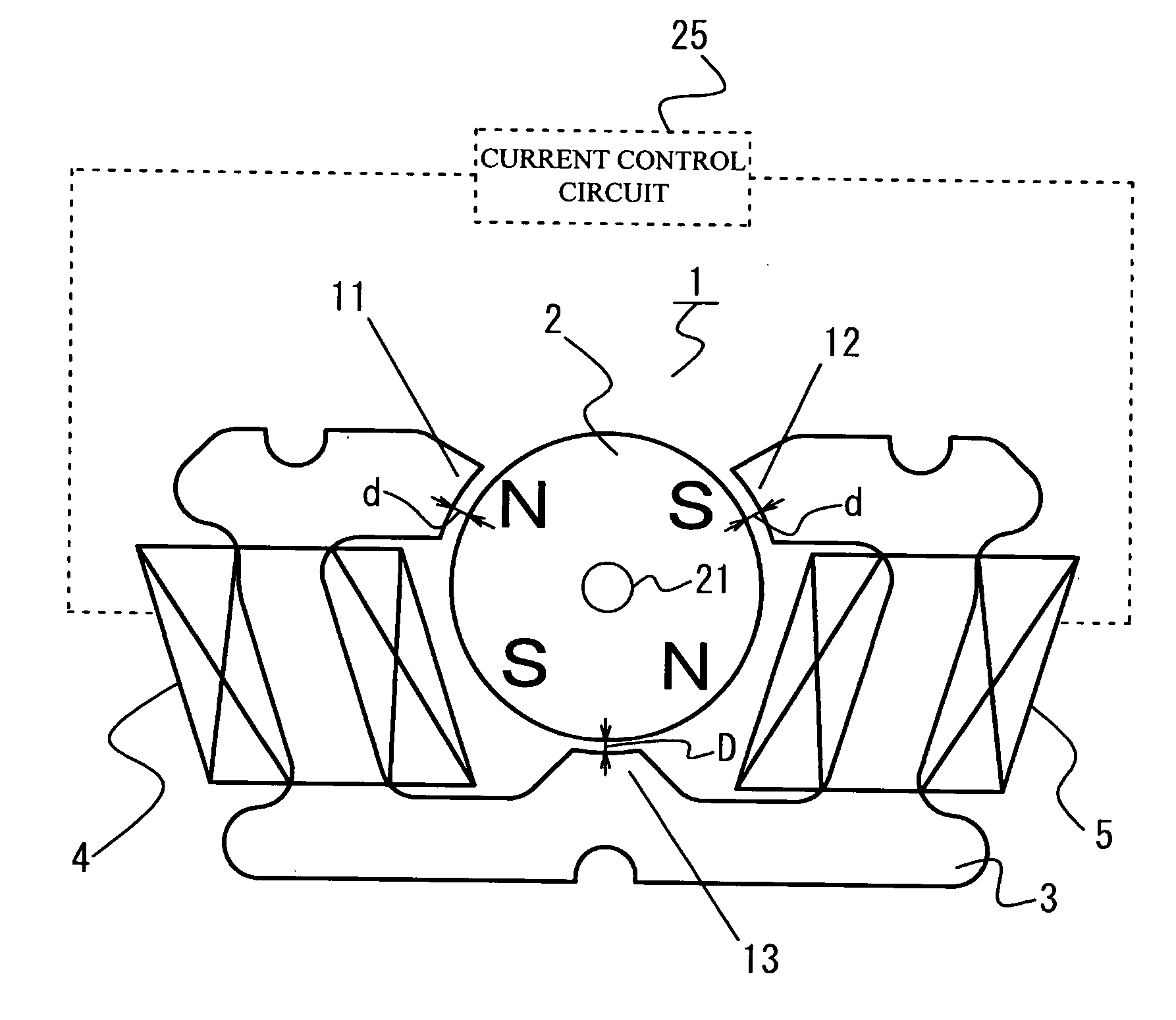
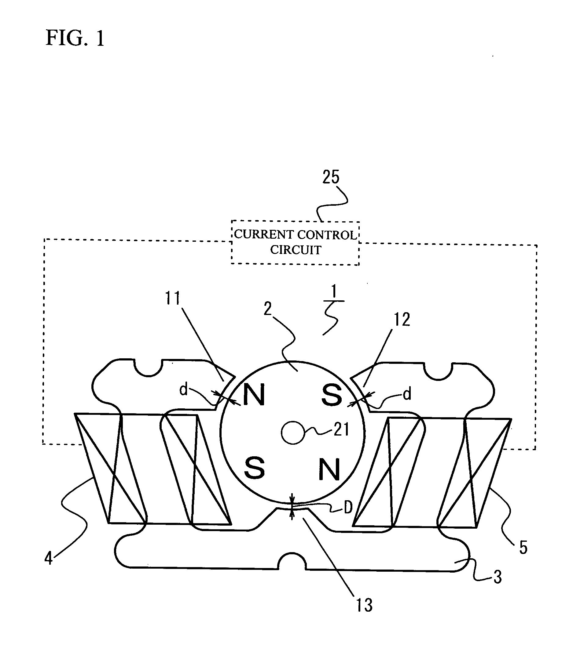
[0018] A description will now be given, with reference to the accompanying drawings, of an embodiment of the present invention. FIG. 1 is a view showing main components of a step motor in accordance with an embodiment of the present invention. A step motor 1 includes a rotor 2 and a stator 3, the rotor 2 being arranged in the center thereof and capable of rotating in both directions, the stator 3 being arranged to face an outer circumference of the rotor 2. The rotor 2 has a cross-section of circle and has a shape of cylinder. The stator 3 is integrally formed to have a plan view of substantially lateral U-shape, and is located in a state that the rotor 2 is housed in an internal space thereof. In addition, the step motor 1 is shown in FIG. 1 with an open end of the lateral U-shape facing upwardly.

[0019] The rotor 2 includes four magnetic poles, which are composed of two North magnetic poles and two South magnetic poles. The rotor 2 is a permanent magnet magnetized in positions whe...


PUM


Abstract

A step motor includes a rotor having four magnetic poles, a first magnetic pole magnetically excited by a first coil, a second magnetic pole magnetically excited by a second coil, and a third magnetic pole magnetically excited by the first coil and the second coil. A gap between the third magnetic pole and the rotor is smaller than that between the first magnetic pole and the rotor and that between the second magnetic pole and the rotor. In the step motor, it is possible to intensify the influence, on the rotor having four poles, of the magnetic fields created from three magnetic poles. Accordingly, this can weaken the magnetic fields set up from the first magnetic pole and the second magnetic pole, which tend to intensify the influence on the rotor, enabling the torque smaller at the time of the rotation start of the rotor.

Description

CROSS-REFERENCE TO RELATED APPLICATIONS [0001] This application is a continuation of and claims priority to U.S. patent application Ser. No. 10 / 562,329, filed Dec. 23, 2005, which claims priority to International Patent Application No. PCT / JP2004 / 009100, filed on Jun. 28, 2004, which claims priority to Japanese Patent Application No. 2003-188980, filed on Jun. 30, 2003, the subject matter of these patent documents is incorporated by reference herein in its entirety.BACKGROUND OF THE INVENTION [0002] 1. Field of the Invention [0003] This invention generally relates to small-sized step motors for use in cameras or the like, and more particularly, to a step motor suitable for use in driving a shutter, lens, barrier, and the like of a camera. [0004] 2. Description of the Related Art [0005] In recent years, cameras have become electronics devices and shutters thereof are driven by the step motors. In addition, cameras are promoted to be small-sized and light-weighted, leading to a demand...

Claims


Application Information

Patent Timeline
Patent Type & Authority Applications(United States)
IPC IPC(8): H02K37/14H02K1/14H02K5/15H02K5/16H02K37/16
CPCH02K1/14H02K37/16H02K37/14H02K5/15
Inventor KAWAMOTO, HISASHIOISHI, SEIICHI
Owner SEIKO INSTR INC
Why Eureka
Try Eureka