Offset correction circuit for voltage-controlled current source

a voltage-controlled current and offset correction technology, applied in the field of power supply systems, can solve problems such as affecting the output current of transconductance amplifiers

Active Publication Date: 2006-10-12
ANALOG DEVICES INT UNLTD
View PDF19 Cites 14 Cited by
  • Summary
  • Abstract
  • Description
  • Claims
  • Application Information

AI Technical Summary

Benefits of technology

[0010] The present disclosure offers novel circuitry and methodology for correcting the offset associated with a voltage-controlled current source. In partic...

Problems solved by technology

However, an offset voltage associated with amplifier circuitry i...

Method used


Image

  • Offset correction circuit for voltage-controlled current source
  • Offset correction circuit for voltage-controlled current source
  • Offset correction circuit for voltage-controlled current source

Examples


Embodiment Construction

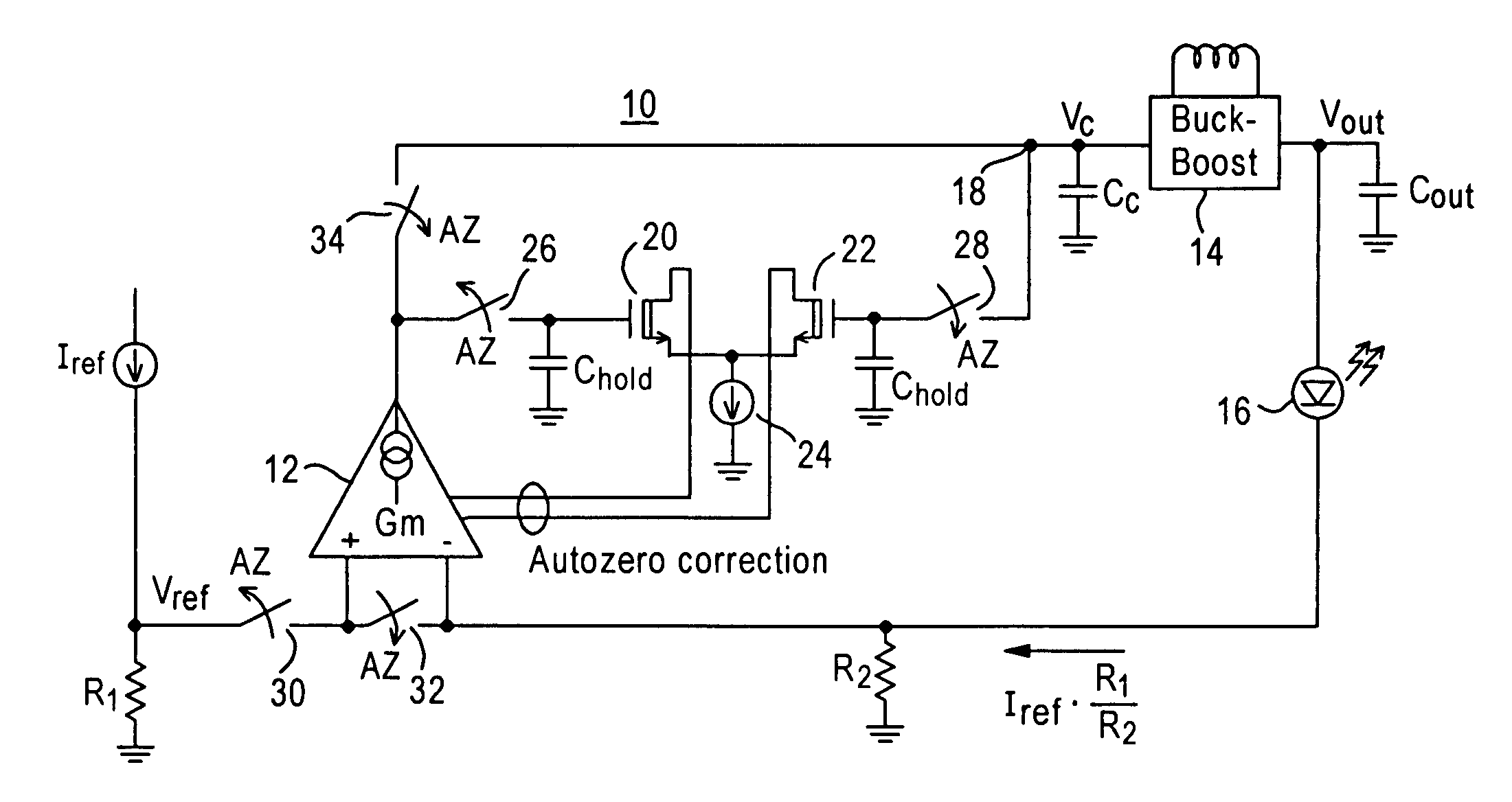
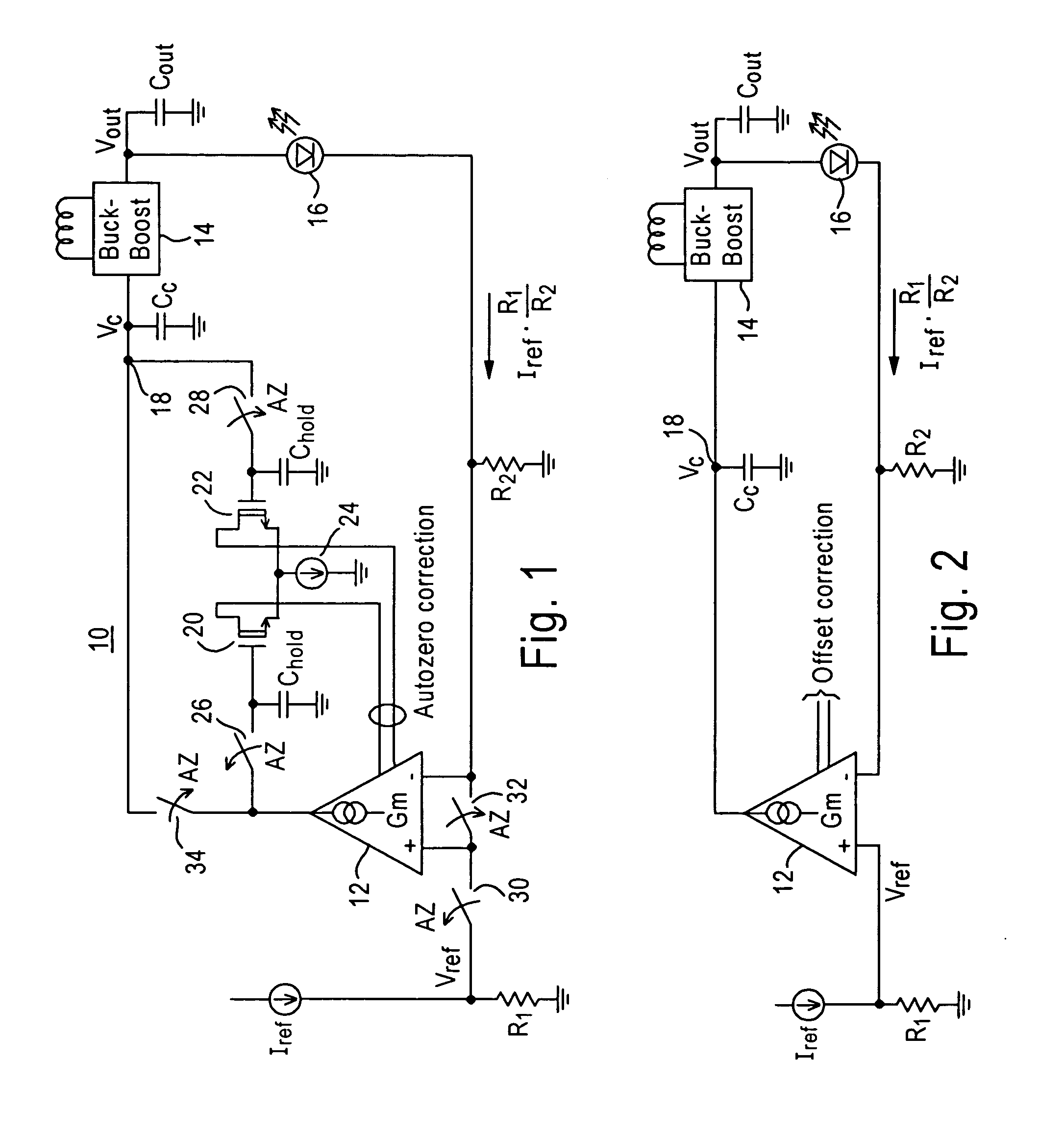
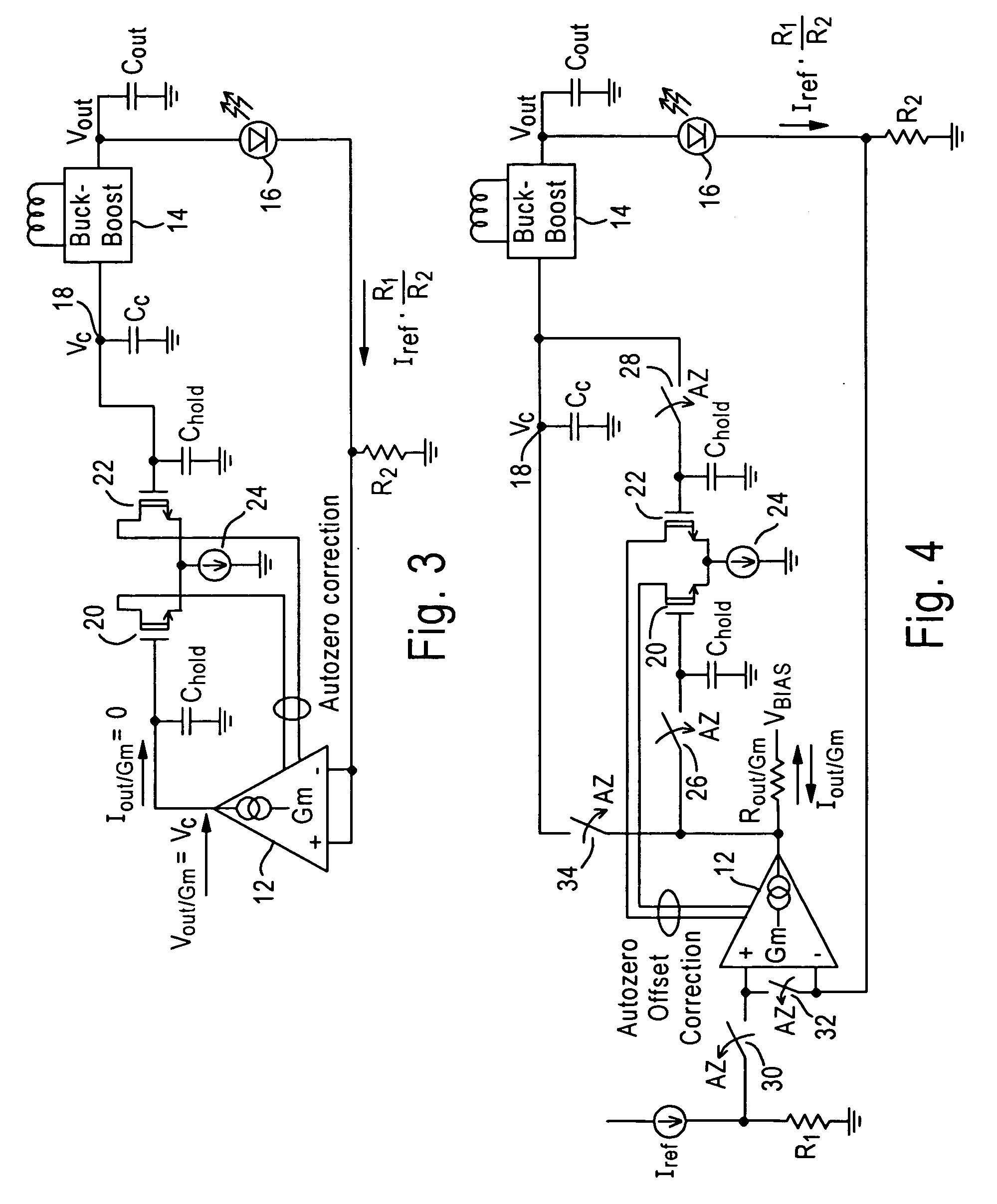
[0028] The present disclosure will be made with the example of a transconductance amplifier that serves as an error amplifier in a buck-boost DC-DC converter regulation loop for a buck-boost LED driver. It will become apparent, however, that the concepts described herein are applicable to any voltage-controlled current source in any power supply system.

[0029]FIG. 1 shows a simplified circuit diagram illustrating a buck-boost LED driver 10 including a transconductance amplifier 12 that serves as an error amplifier in a buck-boost DC-DC converter regulation loop. The output of the transconductance amplifier 12 is coupled to a buck-boost DC / DC converter 14 that generates the output voltage required to drive a LED 16 such as a white LED. An example of the buck-boost DC / DC converter is the LTC®3453 buck-boost converter manufactured by Linear Technology Corporation.

[0030] In particular, the output of the transconductance amplifier 12 is connected to a voltage compensation node 18. The o...


PUM


Abstract

Novel circuitry and methodology are provided for correcting the offset associated with a voltage-controlled current source. An offset correction circuit is coupled to the current source to prevent the output current produced by the current source from deviating from a desired level. The current source may include a transconductance amplifier or a chopper amplifier, and may be configured to produce a zero or non-zero value of the output current.

Description

TECHNICAL FIELD [0001] This disclosure relates to power supply systems, and more particularly, to circuitry and methodology for providing offset correction of a voltage-controlled current source that may serve, for example, as an error amplifier in a buck-boost DC-DC converter regulation loop for a buck-boost light-emitting diode (LED) driver. BACKGROUND ART [0002] A voltage-controlled current source, such as a transconductance amplifier, may convert a difference between voltages to current. The ideal transfer characteristics of a transconductance amplifier is: Iout=Gm(Vin+−Vin−), where [0003] Iout is current at the output of the amplifier, [0004] Gm is the transconductance, [0005] Vin+ is voltage at the non-inverting input of the amplifier, and [0006] Vin− is voltage at the inverting input. [0007] Hence, the transconductance amplifier produces an output current proportional to a difference between voltages at its inputs. The most simple transconductance amplifier consists of a dif...

Claims


Application Information

Patent Timeline
IPC IPC(8): H03F1/02
CPCH05B33/0815Y02B20/347H05B33/0848H05B45/14Y02B20/30H05B45/3725
Inventor VITUNIC, MARK ROBERTHENDERSON, EDWARD LLOYD
Owner ANALOG DEVICES INT UNLTD
Why Eureka
Try Eureka