
Display apparatus and control method thereof

a control method and display technology, applied in the field of display apparatus and control method thereof, can solve the problems of motion blur problem of lcds, requires additional hardware components, and is relatively difficult, and achieves the effect of reducing motion blur and simple operation

Inactive Publication Date: 2006-10-12
SAMSUNG ELECTRONICS CO LTD
View PDF8 Cites 126 Cited by
  • Summary
  • Abstract
  • Description
  • Claims
  • Application Information

AI Technical Summary

Benefits of technology

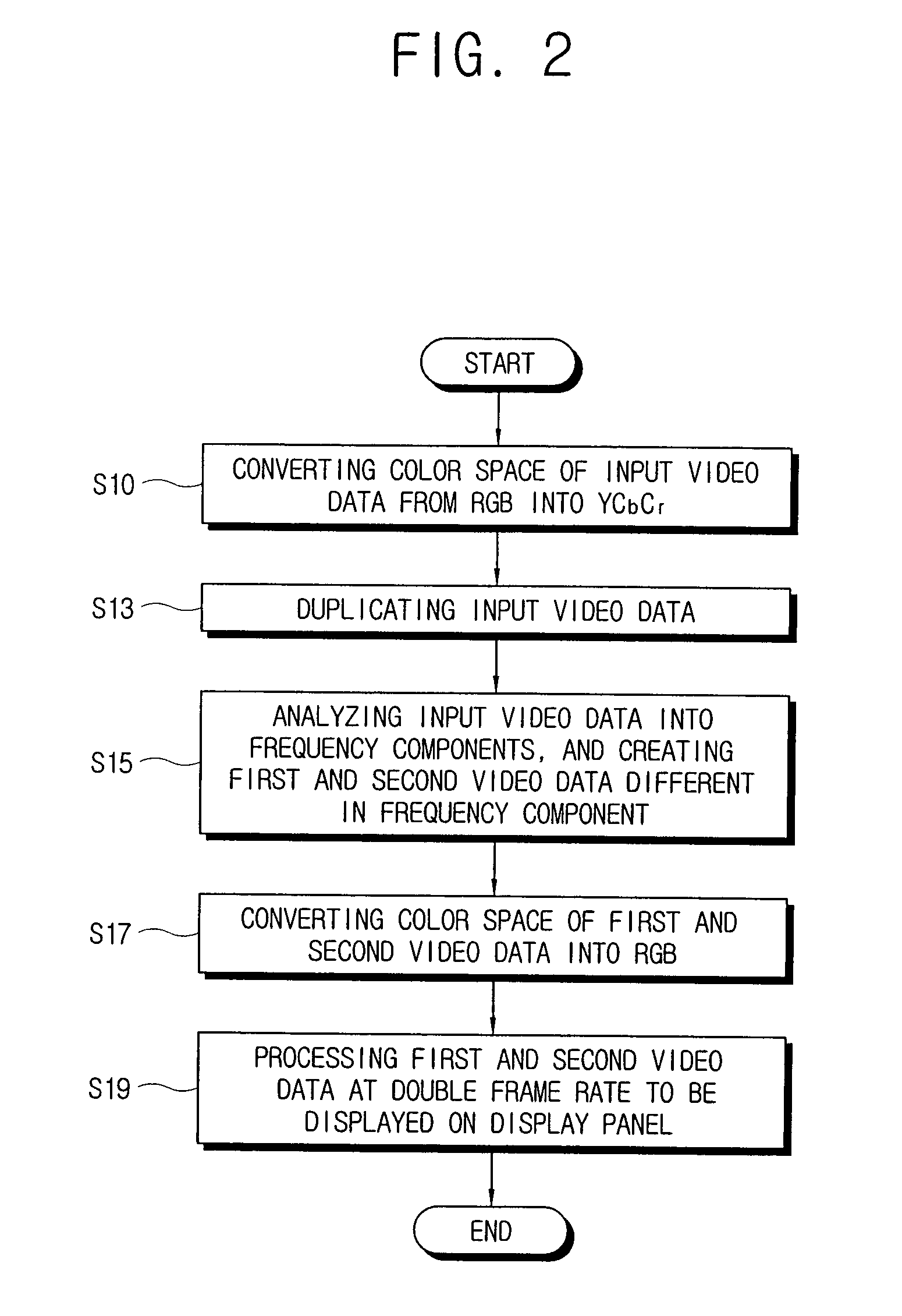
[0012] Accordingly, it is an aspect of the present invention to provide a display apparatus and a control method thereof, in which first video data and second video data are created by analyzing a frequency component of input video data and output in sequence, thereby decreasing a motion blur through a simple operation without requiring additional hardware.

Problems solved by technology

LCDs have a motion blur problem because it has a long response time and the characteristic of the hold-type display.
However, due to prediction requirement this method is relatively difficult, and requires additional hardware components to implement.
However, a low pass filter for a motion blur is a zero cross filter, so that it is practically impossible to implement an ideal inverse filter.
In the MCIF method, a high frequency boost method is used in estimating an ideal inverse low pass filter, but an overshoot problem arises.
However, this black insertion method has a problem of low brightness.
To enhance the brightness of a backlight module, the brightness must be compensated, but there arises problems in that a display panel should be redesigned and the temperature of the backlight module rises in order to compensate the brightness of the backlight module.
The gray level of the first half frame between two frames can be doubled to maintain the brightness, but causes problems due to a gray level limit (0 through 255).

Method used


Image

  • Display apparatus and control method thereof
  • Display apparatus and control method thereof
  • Display apparatus and control method thereof

Examples


Embodiment Construction

[0050] Reference will now be made in detail to exemplary embodiments of the present invention, examples of which are illustrated in the accompanying drawings. The embodiments are described below so as to explain the present invention by referring to the figures.

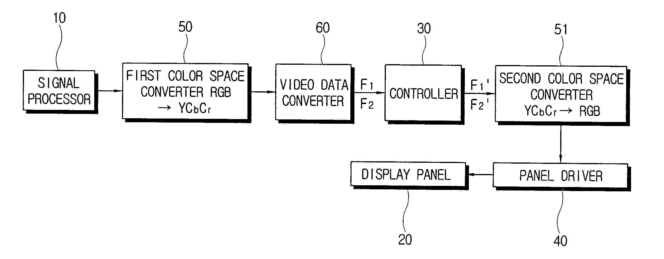
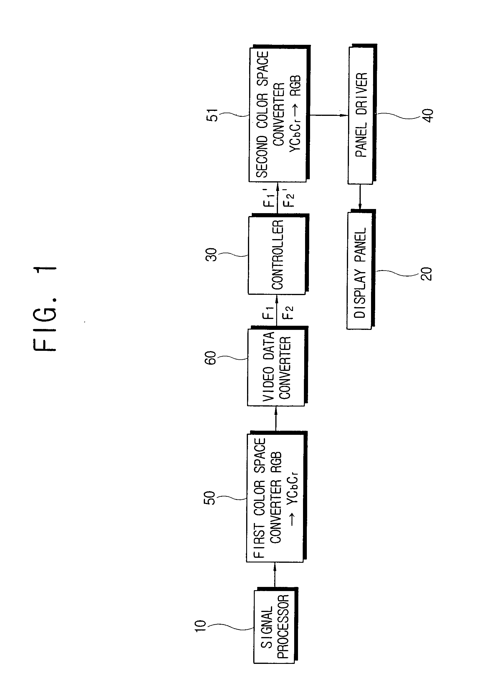
[0051]FIG. 1 is a control block diagram of a display apparatus according to an embodiment of the present invention.

[0052] As shown in FIG. 1, a display apparatus according to an embodiment of the present invention comprises a signal processor 10, a display panel 20, a controller 30, and a panel driver 40.

[0053] The signal processor 10 processes video data input to the display apparatus. Here, the signal processor 10 converts the input video data to have a format compatible with the panel driver 40. According to an embodiment of the present invention, the signal processor 10 comprises a scaler to scale the video data, and a signal converter to convert the input video data to be compatible with the scaler. Here, the signal c...


PUM


Abstract

The present invention relates to a display apparatus comprising a display panel; a controller to analyze input video data into frequency components, and create first and second video data different in the frequency component from each other on the basis of analyzed results; and a panel driver to drive the created first and second video data to be displayed in sequence as images on the display panel. Thus, the present invention provides a display apparatus and a control method thereof, in which first video data and second video data are created by analyzing a frequency component of input video data and output in sequence, thereby decreasing a motion blur through a simple operation without hardware change.

Description

CROSS-REFERENCE TO RELATED APPLICATIONS [0001] This application claims the benefit under 35 U.S.C. §119(a) of Korean Patent Application No. 2005-0030028, filed on Apr. 11, 2005, in the Korean Intellectual Property Office, the entire disclosure of which is hereby incorporated by reference. BACKGROUND OF THE INVENTION [0002] 1. Field of the Invention [0003] The present invention relates to a display apparatus and a control method thereof. More particularly, the present invention relates to a display apparatus capable of decreasing a motion blur and a control method thereof. [0004] 2. Description of the Related Art [0005] The cathode ray tube (CRT) has recently been replaced with new display systems. As an example of alternatives to the CRT, there is a liquid crystal display (LCD) which is being applied to televisions, computer monitors, and the like. Compared to the CRT, the LCD is relatively thin, flat and lightweight. [0006] The CRT and the LCD are significantly different in their d...

Claims


Application Information

Patent Timeline
IPC IPC(8): H04N7/12H04N11/20H04N11/04H04N5/21H04N7/01H04N11/02
CPCG09G3/20G09G3/2022G09G2320/0261G09G2320/10G09G2340/0435G09G2360/16G06T2207/20201H04N5/208G06T5/003G06T5/20G06T2207/10016G06T2207/10024H04N5/205G06T5/73G09G3/36
Inventor CHEN, HAN FENGKWON, OH-JAELEE, SUNG-HEE
Owner SAMSUNG ELECTRONICS CO LTD
Learn More