

Image processing system for preventing forgery
a processing system and forgery prevention technology, applied in the field of image processing system, image processing method, image processing apparatus, can solve the problems of large load necessary to judge whether an original is a copy-inhibited object, low processing speed, and further severe problems, and achieve the effect of efficient judgment of a specific imag
- Summary
- Abstract
- Description
- Claims
- Application Information
AI Technical Summary
Benefits of technology
Problems solved by technology
Method used
Image

Examples
first embodiment
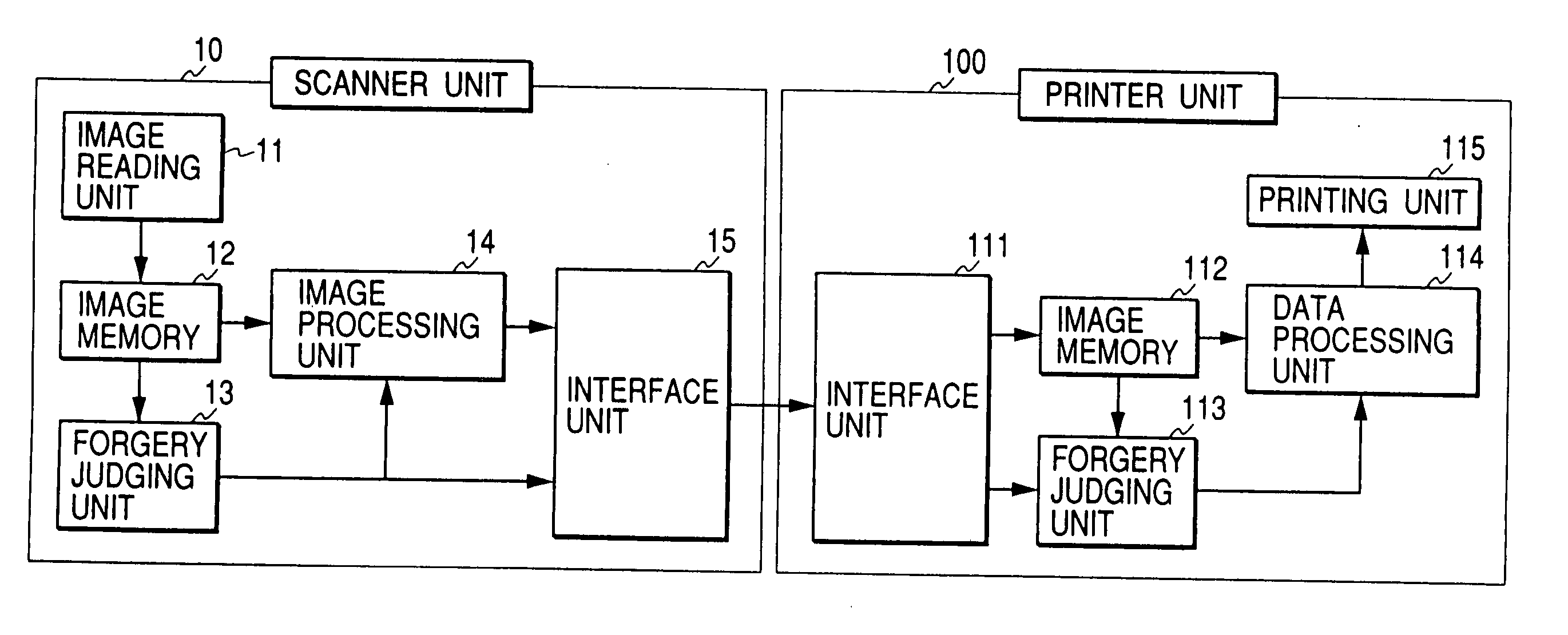
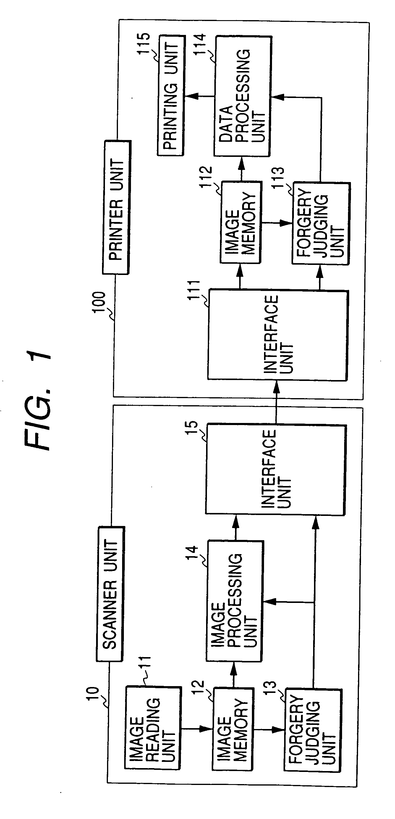
[0045]FIG. 1 is a block diagram of an image processing apparatus according to a first embodiment. In FIG. 1, a scanner unit 10 and a printer unit 100 are connected to each other through an interface unit. Interfaces are Centronics, RS-232C, USB, IEEE1394, and Ethernet interfaces, and there is no limitation on forms of interfaces.
[0046] An image reading unit 11 in the scanner unit 10 optically reads an original set in the scanner unit 10 and outputs three colors, that is, R, G, and B of color image data. Image memory 12 stores the color image data outputted from the image reading unit, and a forgery judging unit 13 is connected to the image memory 12. An image processing unit 14 is connected to the image memory 12, an interface unit 15 is connected to the forgery judging unit 13 and image processing unit 14, and data is sent from the scanner unit 10 to the printer unit 100 through the interface unit 15. In the printer unit 100, an interface unit 111 receives the data sent from the s...
second embodiment
[0063] Next, a second embodiment will be described. The second embodiment is such an example that the operation flow of the printer unit 100 in the first embodiment is modified, and this is shown in FIG. 4.
[0064] In FIG. 4, the printer unit 100 inputs a data signal, outputted from a scanner unit, from the interface unit 111 (step S11). Next, it is judged at step S13 whether a mismatch signal is present in the data signal inputted from the interface unit. If the mismatch signal is present, the flow goes to step S12, input image data is written in the image memory 112, and printing operation is started (step S18).
[0065] In addition, writing of the input image data in the image memory 112 that is performed at the step S12 is controlled so that, just after writing with volume required in the data processing unit 114 and printing unit 115 that are subsequent stages is completed, the flow goes to step S18, data is read from the image memory 112, and printing operation is started. In thi...
third embodiment
[0070] Next, a third embodiment will be described. In the third embodiment, a scanner unit and a printer unit are connected via a network, which is different from the first and second embodiments where the scanner unit and printer unit are connected in one-to-one relation.
[0071]FIG. 5 is a block diagram of the third embodiment. In FIG. 5, a scanner unit-A 10, and a printer unit 100 have respectively the same functions as those of the scanner unit 10 and printer unit 100 that are described in the first embodiment. Therefore, the same reference numerals are assigned to the blocks having the same functions.
[0072] This embodiment is configured so that devices connected to a network cable 40 in FIG. 5 input and output each data signal between respective devices via the network cable 40. A scanner unit-B 20 in FIG. 5 is a scanner not having a forgery judging unit, and other components are the same as those of a scanner unit-A 10. In addition, a computer 30 in FIG. 5 is connected to the ...
PUM
 Abstract
Description
Claims
Application Information