Light emitting panel

a technology of light emitting panels and light sources, applied in the direction of lighting and heating apparatus, measurement apparatus components, applications, etc., can solve the problems of poor color rendition, ccfl and electro-luminescent and edge-lit light emitting panels are not without their drawbacks

Active Publication Date: 2006-10-12
AVAGO TECH INT SALES PTE LTD
View PDF3 Cites 17 Cited by
  • Summary
  • Abstract
  • Description
  • Claims
  • Application Information

AI Technical Summary

Benefits of technology

[0007] In one embodiment, a light emitting panel comprises a base panel having a plurality of light emitting elements mounted thereon. Each of the light emitting elements produces an illumination pattern having a region of substantially uniform intensity that extends over a radiation angle of at least about 60°. One or more light conditioners are positioned adjacent the base panel to receive and condition light produced by the light emitting elements.

Problems solved by technology

Unfortunately, however, CCFL and electro-luminescent panels are not without their disadvantages, including poor color rendition.
In addition, they may involve the use of hazardous materials, such as mercury.
Unfortunately, edge-lit light emitting panels are not without their drawbacks.
For example, the placement of the LEDs along the edges of an edge-lit panel limits the ability to dissipate heat produced by the LEDs.
The edge-lit configuration also limits the maximum size of the panel, in that the number of LEDs that may be used to illuminate the panel increases linearly with the edge length, but the area that must be illuminated increases as the square of the edge length.
Consequently, edge-lit panels are typically limited to panels having small areas.
While back-lit panels do not suffer from the brightness limitations of edge-lit designs, and they may be used with panels having larger areas, it has proven difficult to effectively diffuse the light from the individual LEDs so that the panel appears to be evenly illuminated.
Disadvantageously, however, this increases the cost of the panel as more LEDs must be used.
The closer spacing of the LEDs can also create heat dissipation problems.
However, increased light diffusion typically represents a decrease in efficiency, thereby reducing the brightness of the panel or requiring the use of more or brighter LEDs to compensate for the efficiency loss associated with the increased diffusion.

Method used


Image

  • Light emitting panel
  • Light emitting panel
  • Light emitting panel

Examples


Embodiment Construction

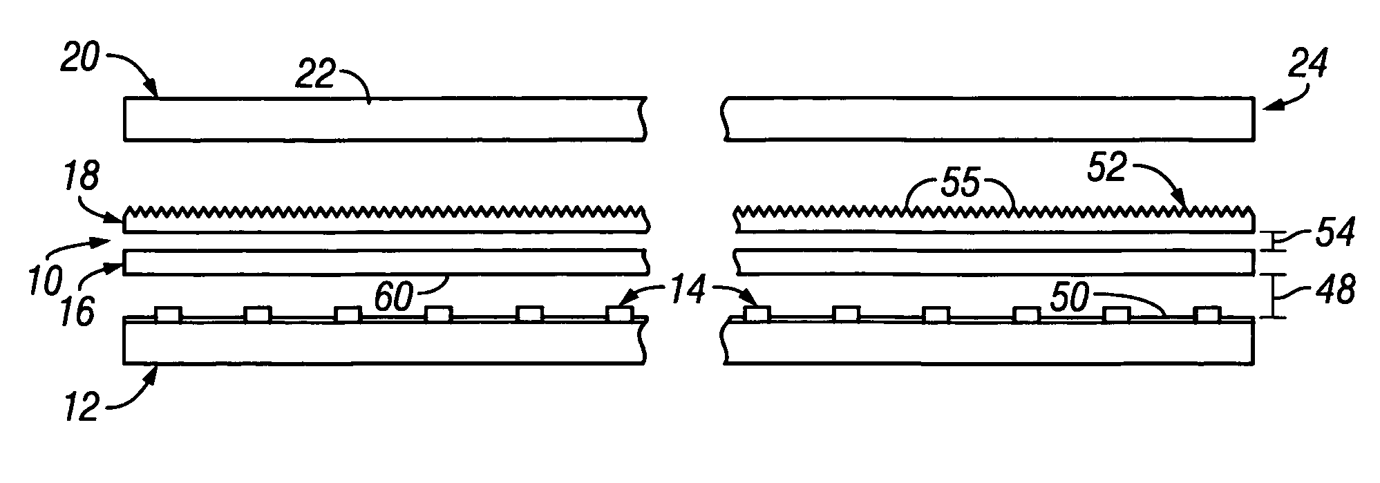
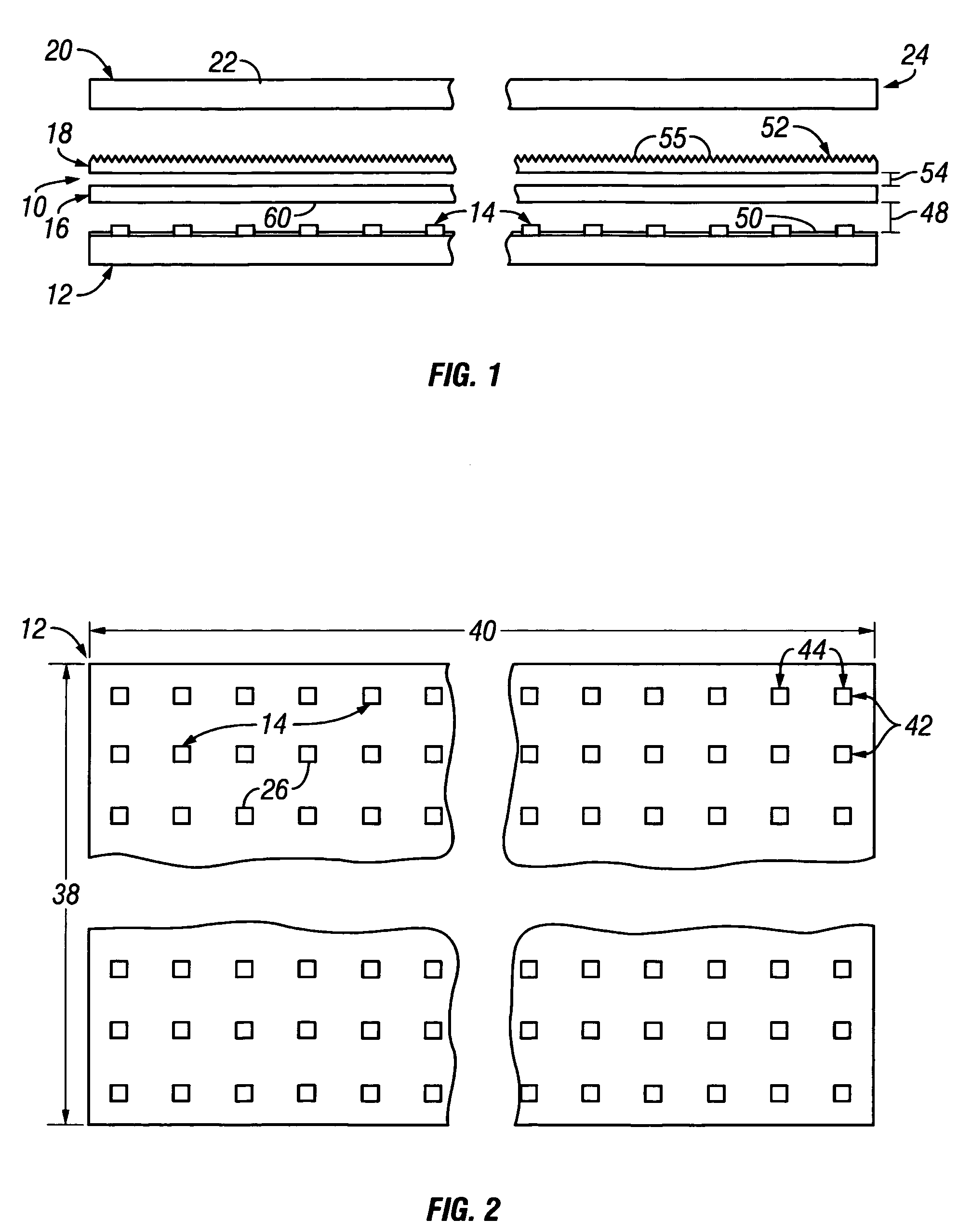
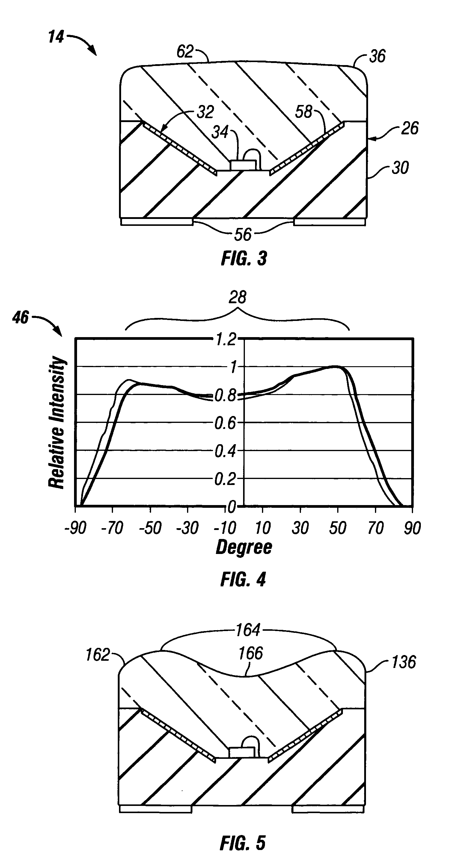
[0015] An exemplary light emitting panel 10 is shown in FIGS. 1 and 2 and may comprise a base panel 12 having a plurality of light emitting elements 14 thereon. As will be described in greater detail below, each of the light emitting elements 14 produces an illumination pattern 46 that comprises a region 28 of substantially uniform intensity that extends over a large radiation angle (e.g., at least about 60°, and typically at least about 100°). See FIG. 4. One or more light conditioners 16, 18 are positioned adjacent the base panel to receive and condition light produced by the various light emitting elements 14. The light conditioners may comprise a diffuser 16 that is positioned adjacent the base panel 12 so that the diffuser 16 receives and diffuses light produced by the various light emitting elements 14 provided on the base panel 12, and a brightness enhancer 18 that is positioned adjacent the diffuser 16. The brightness enhancer 18 collects diffused light from the diffuser 16 ...


PUM


Abstract

In one embodiment, a light emitting panel includes a base panel and a plurality of light emitting elements mounted to the base panel. Each of the light emitting elements produces an illumination pattern having a region of substantially uniform intensity that extends over a radiation angle of at least about 60°. One or more light conditioners are positioned adjacent the base panel to receive and condition light produced by the light emitting elements.

Description

BACKGROUND [0001] Light emitting panels are commonly used as backlights for display systems (e.g, liquid crystal displays), although they may be used for other purposes as well. Light emitting panels commonly used for backlighting displays include cold cathode florescent lamps (CCFL) and electro-luminescent panels. These types of light emitting panels are advantageous in that they provide substantially uniform illumination over the entire area of the panel, thus providing even illumination for the display. Unfortunately, however, CCFL and electro-luminescent panels are not without their disadvantages, including poor color rendition. In addition, they may involve the use of hazardous materials, such as mercury. [0002] Partly in an effort to address the shortcomings of CCFL and electro-luminescent panels, light emitting panels have been developed that utilize light emitting diodes (LEDs) as the light sources. Besides being mercury-free, LED light emitting panels typically provide bett...

Claims


Application Information

Patent Timeline
Patent Type & Authority Applications(United States)
IPC IPC(8): B60Q1/26F21K99/00H01L33/54
CPCG02F1/133603G02F1/133611G02F2001/133607H01L33/54H01L2224/48091Y10S362/80H01L2924/00014G02F1/133607
Inventor MOK, THYE LINNTAN, SIEW KIMNG, SHIN WEN
Owner AVAGO TECH INT SALES PTE LTD
Why Eureka
Try Eureka