Optical pickup unit and information recording apparatus using the same

a technology of information recording apparatus and optical pickup unit, which is applied in the direction of data recording, instruments, disposition/mounting of heads, etc., to achieve excellent control of the position of an objective lens, stably recorded on and reproduced

Inactive Publication Date: 2006-10-12
RICOH KK
View PDF12 Cites 2 Cited by
  • Summary
  • Abstract
  • Description
  • Claims
  • Application Information

AI Technical Summary

Benefits of technology

[0019] Accordingly, it is a general object of the present invention to provide an optical pickup unit in which the above-described disadvantage is eliminated.
[0020] A more specific object of the present invention is to provide an optical pickup unit capable of obtaining excellent sub light beam signals from a multilayer information recording medium in which the direction of the spiral of a guide groove is different on each recording surface, and recording information on and reproducing information from the recording medium using stable signals such as a differential push-pull signal and a lens position signal obtained from the excellent sub light beam signals.
[0023] According to one aspect of the present invention, each sub light beam is disposed in the area of a recorded part where information has been recorded by a main light beam or in the area of an unrecorded part on a recording surface of a multilayer information recording medium. Accordingly, it is possible to obtain an excellent signal without a difference in reflectivity in each sub light beam.
[0027] According to one aspect of the present invention, with respect to a multilayer information recording medium in which the direction of the spiral of a guide groove is different in each recording surface, it is possible to control the position of an objective lens at the time of a high-speed seek operation with respect to each recording surface.
[0028] According to one aspect of the present invention, with respect to a multilayer information recording medium in which the direction of the spiral of a groove is different in each of its recording surfaces, excellent sub light beam signals may be obtained with respect to each recording surface. Further, an excellent differential push-pull signal, lens position signal, and track cross signal without an offset may be obtained with respect to each recording surface during recording even if there is a difference in reflectivity between an unrecorded part and a recorded part. As a result, it is possible to perform excellent control of the position of an objective lens so that information can be stably recorded on and reproduced from the multilayer information recording medium with accuracy.

Problems solved by technology

That is, in the case of recording information on a multilayer information recording medium having an OTP structure, the technique of Japanese Laid-Open Patent Application No. 2004-164720 has a problem in that an offset is caused in one of the recording layers of the recording medium.

Method used


Image

  • Optical pickup unit and information recording apparatus using the same
  • Optical pickup unit and information recording apparatus using the same
  • Optical pickup unit and information recording apparatus using the same

Examples


first embodiment

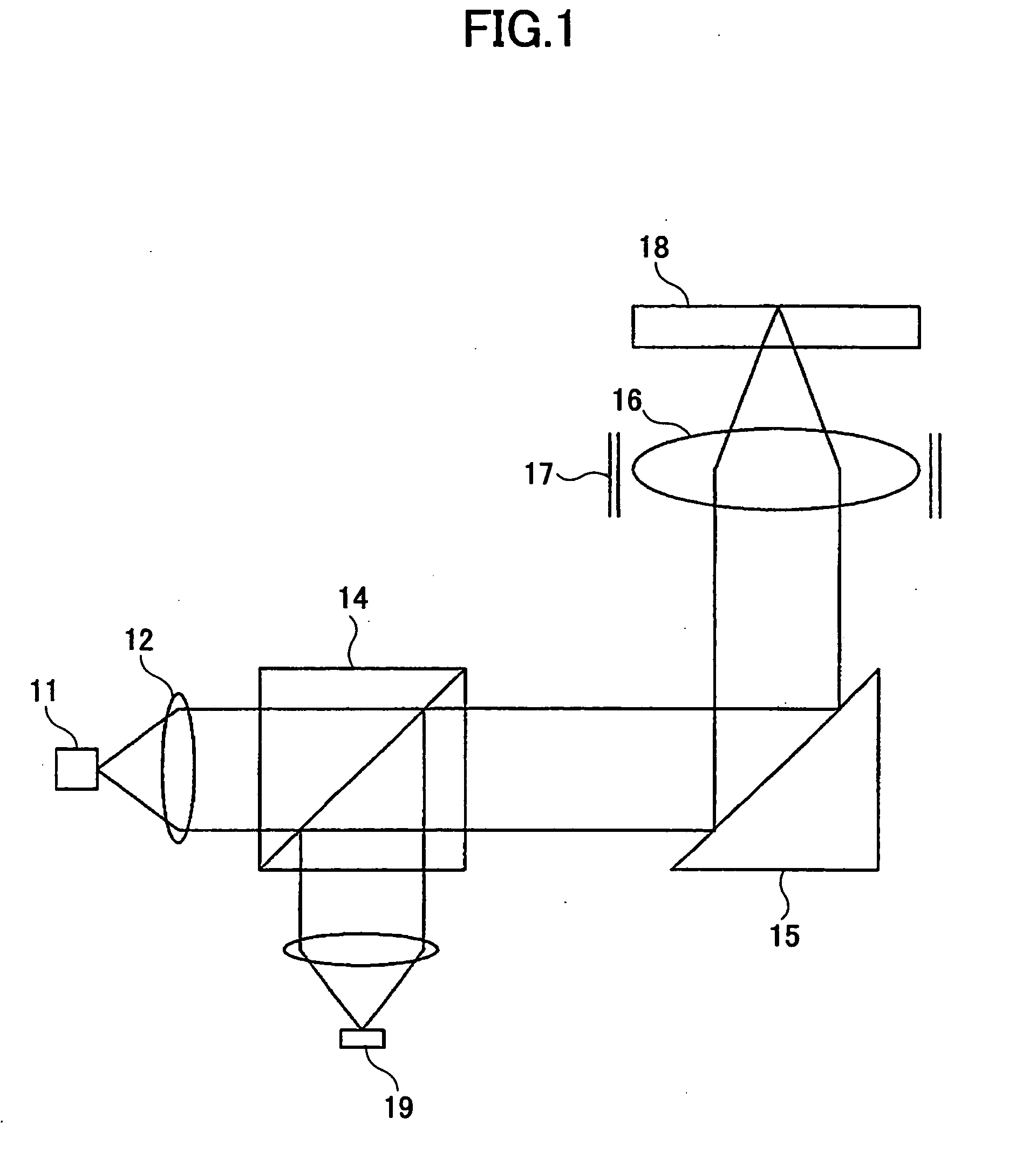
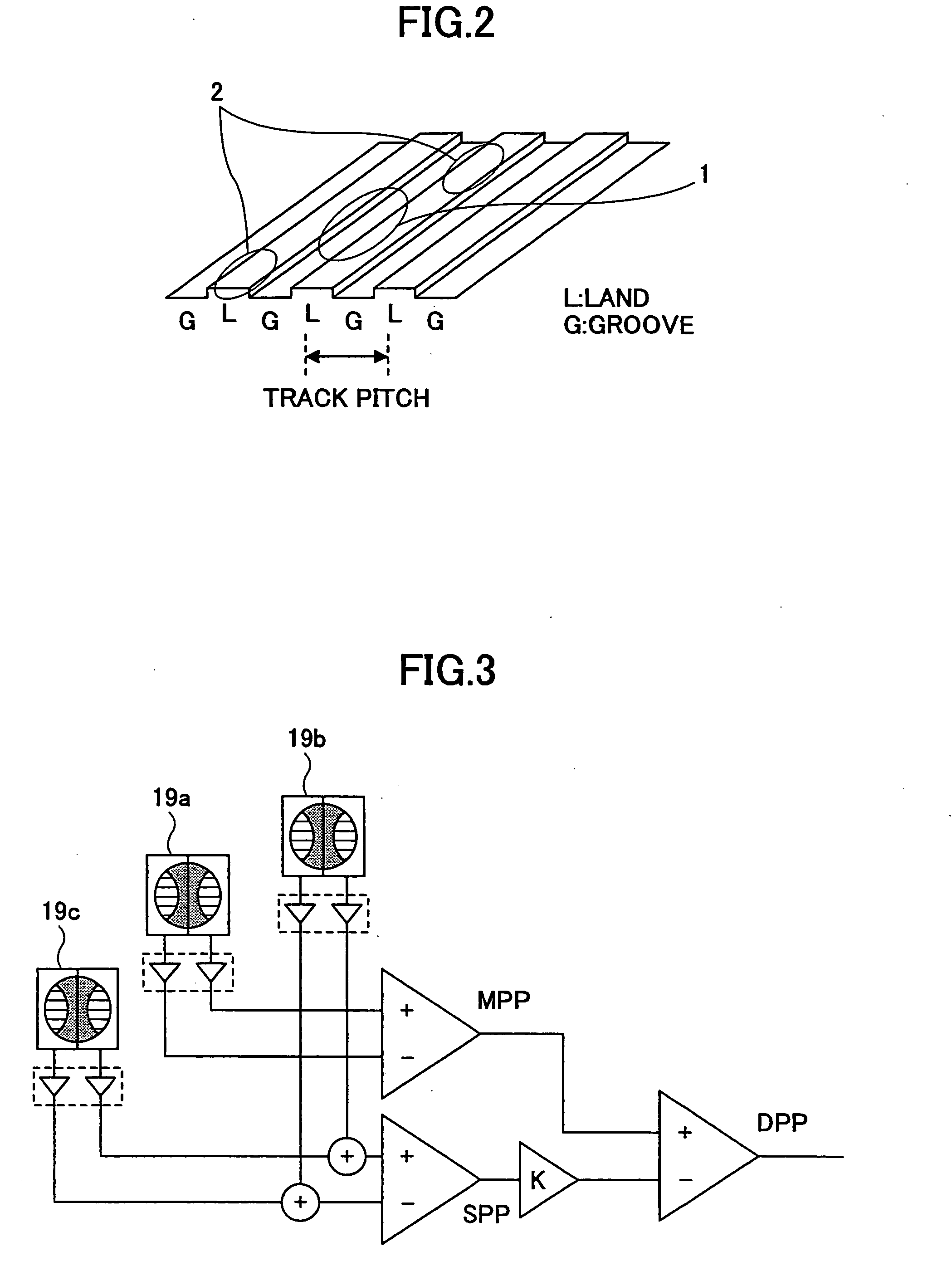
[0043]FIGS. 7A and 7B are diagrams each showing a disposition of the main light beam 1 and the sub light beams 2a and 2b focused onto a recording surface of a multilayer information recording medium (a double layer disk) according to the present invention. FIG. 7A shows a state where each of the beams 1, 2a, and 2b is focused onto the recording surface (L0 layer, FIG. 5) on the objective lens side. In FIG. 7A, information is recorded on the recording surface in a direction from the center to the periphery of the disk. The double layer disk rotates about the disk center. In FIG. 7A, the double layer disk rotates clockwise so that the recording surface is scanned counterclockwise by the beams 1, 2a, and 2b. Accordingly, data is recorded (the recorded part 5 is formed) on the center (inner) side and the trailing (rear) side of the main light beam 1 in the optical disk scanning direction. The data is recorded on a groove. Therefore, the main light beam 1 is focused into a spot on the gr...

second embodiment

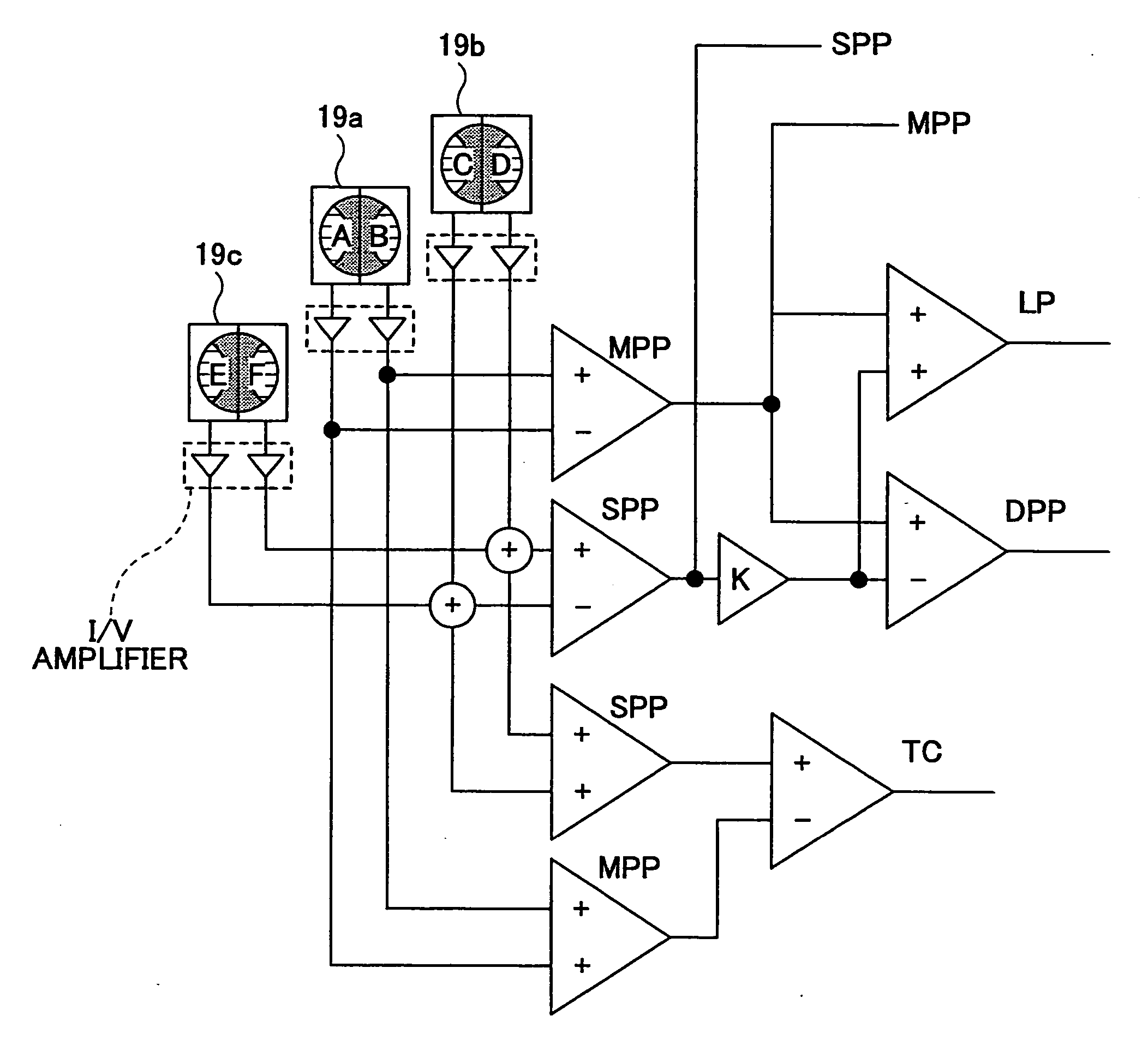
[0091]FIG. 11 is a block diagram showing an information recording apparatus according to the present invention. Referring to FIG. 11, the double layer disk 18a has each of its recording surfaces rotated in the same direction by a spindle (SP) motor 20. An optical pickup unit 10 according to the present invention receives a main light beam and two sub light beams reflected from the double layer disk 18a on the above-described divided light receiving surfaces A through F of the divided light receiving elements 19a through 19c (FIG. 10). The received light beams are subjected to photoelectric conversion in the corresponding divided light receiving elements 19a through 19c so as to be output to a signal calculator 21. In the signal calculator 21, the outputs of the optical pickup unit 10 are converted into voltage values in I / V amplifiers 21a, and the voltage values are fed to each of a DPP calculation circuit 21b, an LP calculation circuit 21c, and a TC calculation circuit 21d. The DPP...


PUM

PropertyMeasurementUnit
refractive indexaaaaaaaaaa
distanceaaaaaaaaaa

Abstract

An optical pickup unit for recording information on and / or reproducing information from a multilayer information recording medium including multiple recording surfaces in each of which a guide groove on which the information is to be recorded is spirally formed is disclosed. The optical pickup unit includes a light source, a diffraction element configured to split the light beam emitted from the light source into a main light beam and first and second sub light beams, an objective lens for focusing the main and sub light beams onto a recording surface of the multilayer information recording medium, and multiple light receiving elements each divided into light receiving parts so as to receive the main and sub light beams reflected from the recording surface. The focused first and second sub light beams are disposed at respective positions at least 3 / 2 tracks away from the focused main light beam on the recording surface.

Description

CROSS-REFERENCE TO RELATED APPLICATION [0001] The present application is a U.S. continuation application filed under 35 U.S.C. 111(a) claiming benefit under 35 U.S.C. 120 and 365(c) of PCT International Application No. PCT / JP2005 / 019153, filed on Oct. 12, 2005, which claims priority to Japanese Priority Patent Applications No. 2004-302662, filed on Oct. 18, 2004, and No. 2005-063861, filed on Mar. 8, 2005. The entire contents of the foregoing applications are hereby incorporated by reference.BACKGROUND OF THE INVENTION [0002] 1. Field of the Invention [0003] The present invention relates generally to optical pickup units and information recording apparatuses, and more particularly to an optical pickup unit recording information on and reproducing information from the recording surface of a multilayer information recording medium using the differential push-pull method detecting and controlling the position of an emitted light beam, and an information recording apparatus using the sa...

Claims


Application Information

Patent Timeline
Patent Type & Authority Applications(United States)
IPC IPC(8): G11B7/00
CPCG11B7/007G11B7/0903G11B2007/0013G11B7/1353G11B7/0943G11B7/09
Inventor OGATA, TETSUYAMIKAMI, TATSUO
Owner RICOH KK
Why Eureka
Try Eureka